![]()

(or what the editor gets up to during winter hibernation)
|
|
|
|
|
(or what the editor gets up to during winter hibernation) |
||
|
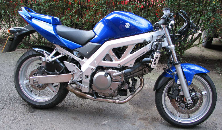
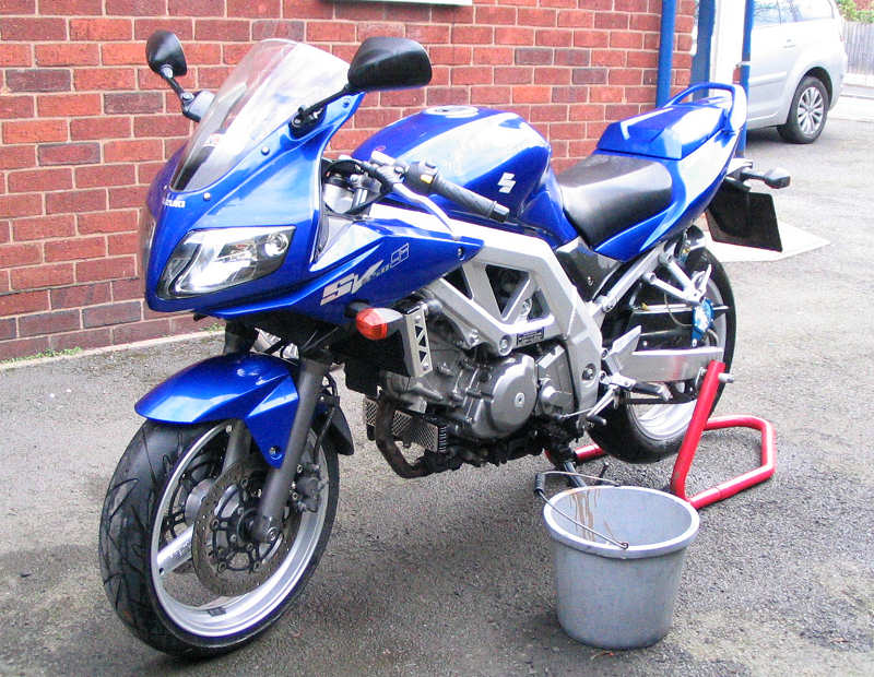
2006 - A new face makes it's first appearance on this site. I thought long and hard about what bike I should buy to replace my 1999 SV650s. I read tests, listened to other peoples opinions but the train of thought still came back to the SV. All the reasons why I bought the mk1 SV were still valid as my requirements were the same. So the hunt started for a mk2 SV650s. In October 2006 I purchased a mint condition blue SV650s in 2004 spec. It had already covered 4.5k miles and was quite clean, although there is the odd nasty. I rode the bike up to the first week in January and then put her in the garage for the annual de-grime, de-grease and de-rust. I also had a few mods to makes as well.
|
|
|
Winter 2005-2006
|
|
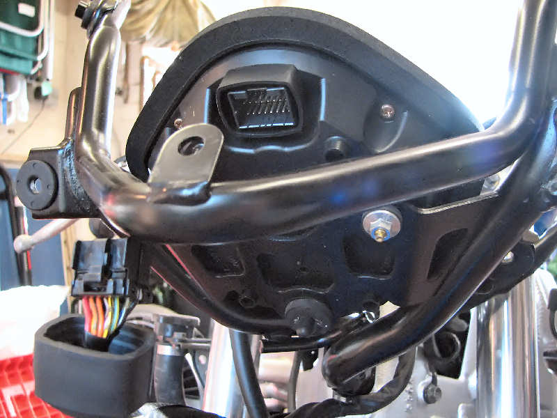
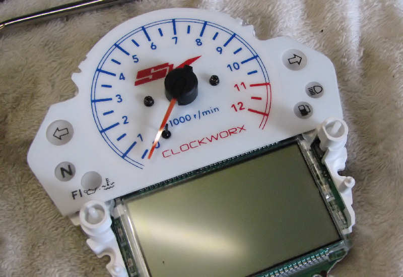
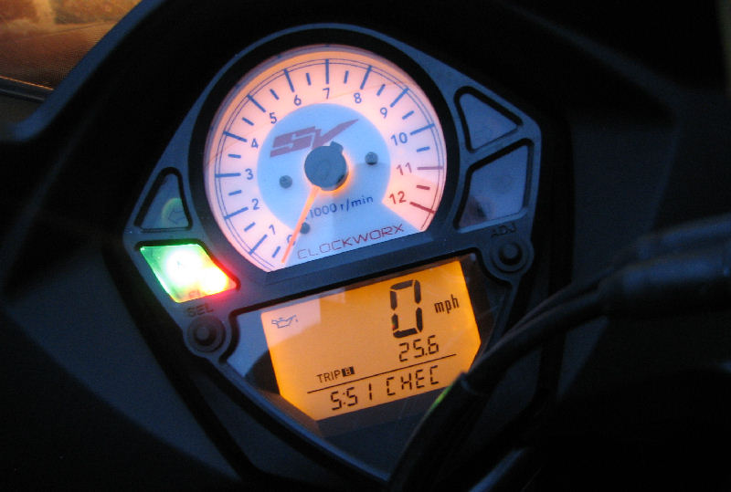
| I've never liked the design of the rev counter face, it always looked cheap to me. Much prefer the mk1 version. So when I saw the Clockworx face, I had to get it. Here's how it fitted. First remove fairing and instrument dash. This leaves the gauge unit in the frame Remove the mulitplug and then the two bolts and the unit removes easily |
|
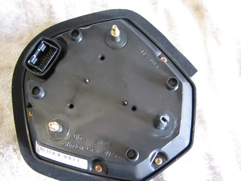
| Put the guage on something soft to protect it and remove the 5 cross head screw from the rear |
|
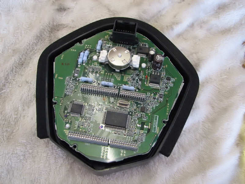
| And your left looking at this. Remove the circuit board and turn over |
|
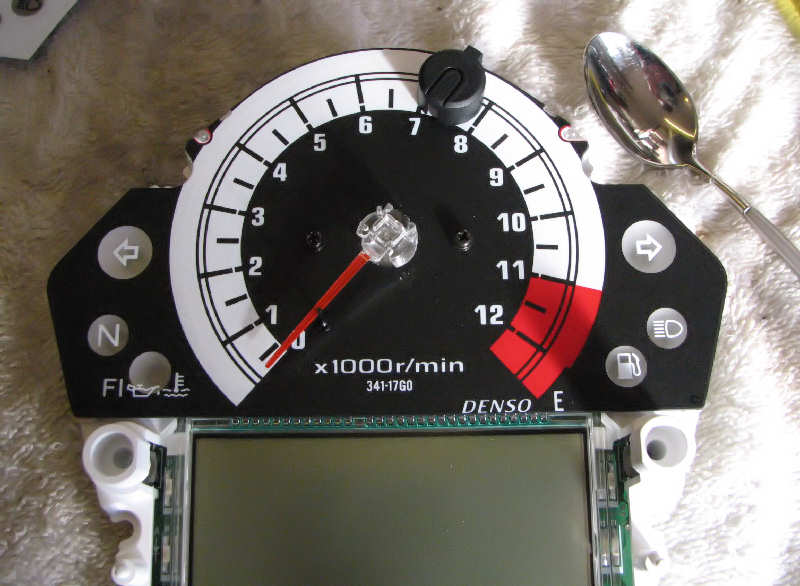
| Prise off the black cap in the centre of the needle The prise off the needle. Be very careful as the needle shaft is quite thin and can easily bend. The instruction advise using two teaspoons as levers, one on each side pivoting on the two black screw heads. This will apply equal pressure on both side as you depress the spoons. Remove the two black screws and the face can be lifted away. |
|
| Remove the needle stop (black pin) from the old clock face. The hole for this pin on the new face was slightly too small, but a quick widening with a drill bit (by hand) soon sorted that. The new face was dropped into position and the screws re-fitted. |
|
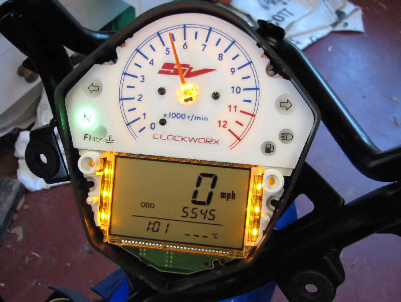
| Being and electronic rev counter, there isn't the usual spring loaded return on the needle, so whilst messing around I had moved the needle before removal. The question now was what was it pointing at before, so I could put it in the same position? Also it may not be spring loaded but the needle did move by itself on occasion. I put the needle back where I thought it was and put the unit back together again. I help the curcuit board face up dropped into the two plastic pins that operate the reset and select buttons and also a piece of black trim that goes around the LCD. Put on the top and then turned over and placed on the back and re-fitted screw. I then connected to the bike and watched with amusement as the bike idled at 5000 rpm. I think the needle is in the wrong place! |
|
| So I took it all apart again and refitted to the bikes curcuit as shown in the photo. At this point the needle wasn't pushed fully home. So once the bike was running and at idle speed. I popped off the needle and refitted it at 1000 rpm. I then put everything back together properly and this is how the finished unit looks |
|
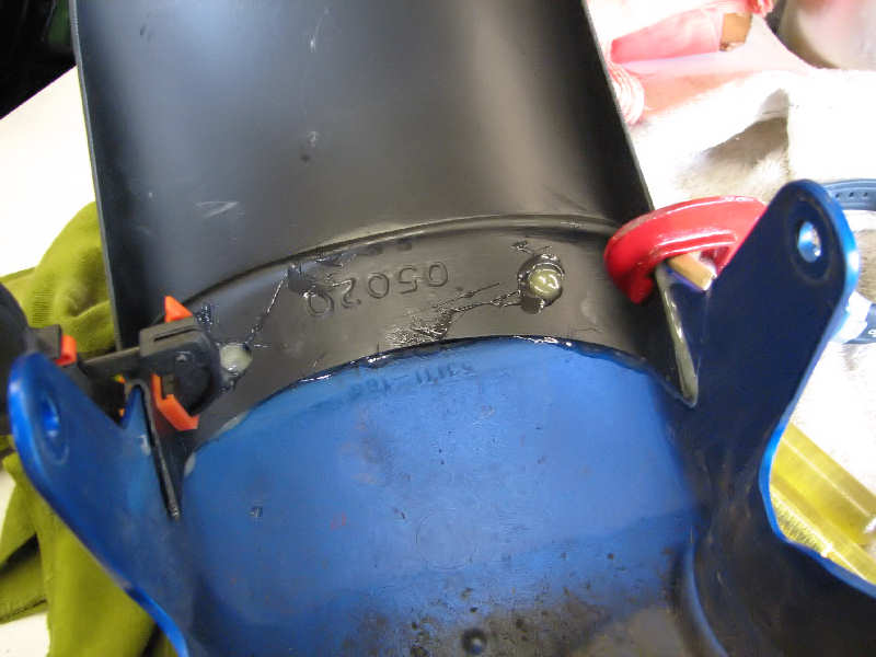
| Next job was to fit the Pyramid fenda extenda. I cleaned up the inside of the mudguard and then roughened up the contact areas. Applied a liberal coating of Aradite and clamped the guard and extenda together and left overnight. |
|
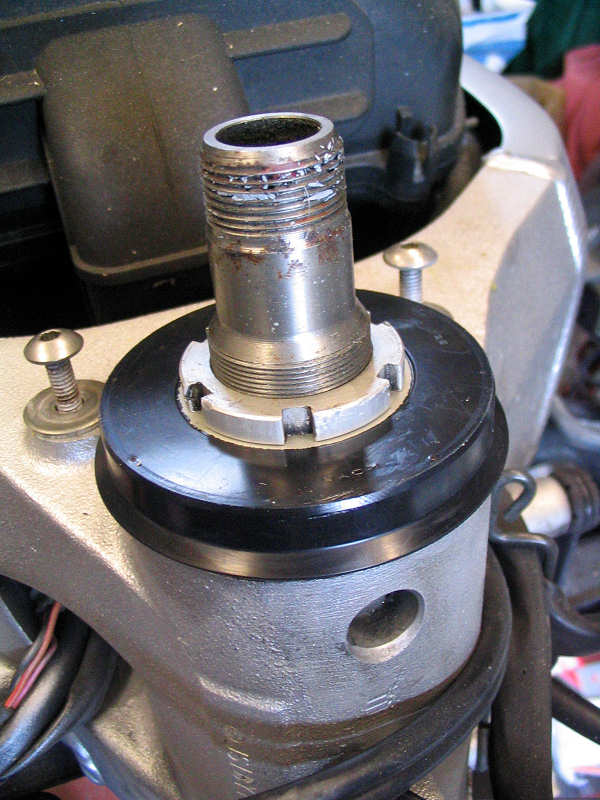
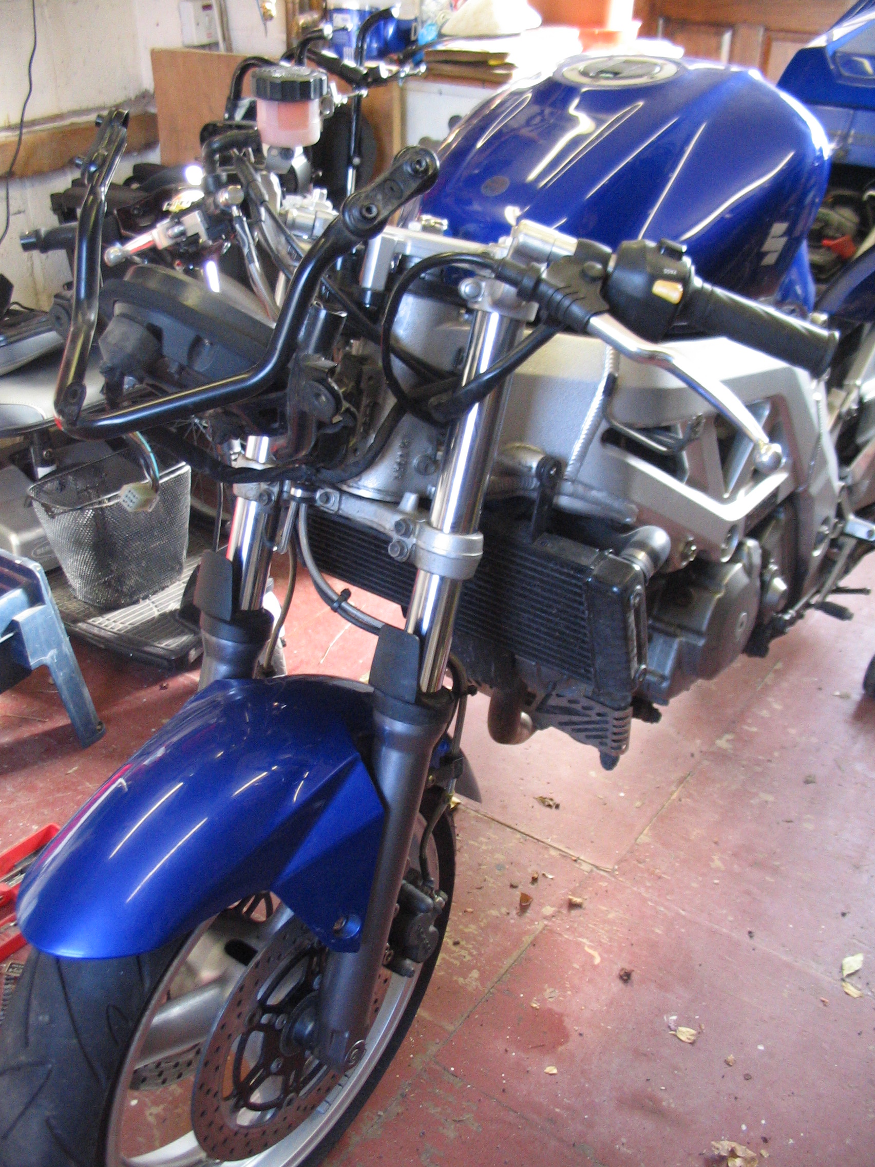
| This gave me a chance to check the front end out for problems. Didn't take too long to notice the surface rust on the bottom yoke. Note also the small plastic guard. I can only assume that the shortness of the front mudguard has caused this problem. I assume the plastic gaurd is also there for the same reason as the rubber flap under the radiator, to keep water away from the front spark plug. Why not fit a proper mudguard in the first place. Classic case of style over function. I was going to dismantle the forks so I could clean and spray this part. I hit a snag at this point. The front axle has a hex head instead of the usual bolt head. This looks neat but I don't have a 12mm Allen key. I thought there must be one in the supplied toolkit, for puncture use, even the owners manual shows you how to remove the front wheel, so it's considered a novice job. No Allen key in the toolkit! I dug out the manual and referred to the wheel removal section and it quoted "special Suzuki tool required". For Pete's sake..... What a stupid decision. How much would it cost to include a 12mm key in the toolkit. So it's off the tool shop on Monday. |
|
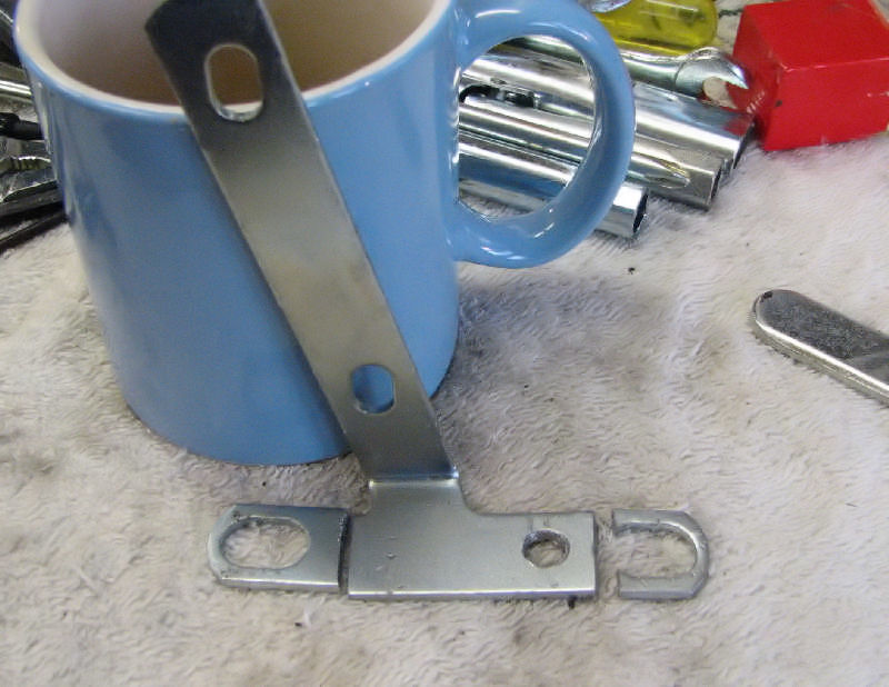
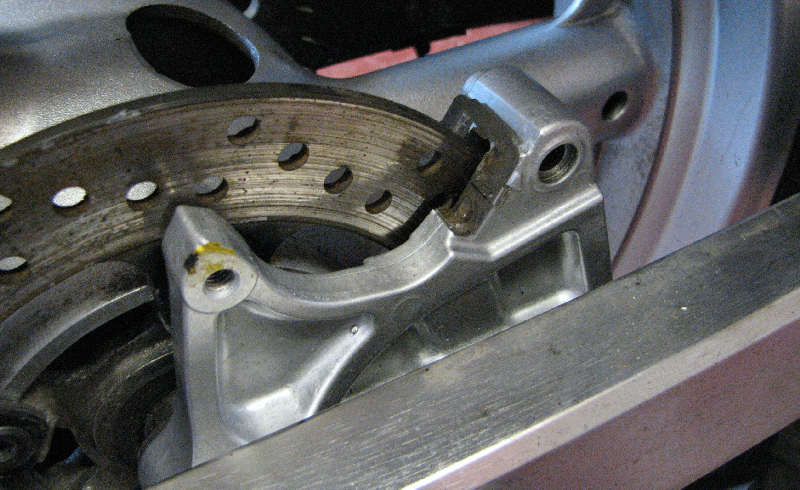
| Next job was to fit the Powerbronze hugger. I bought this on Ebay even though it was listed for a naked mk2 SV. I couldn't see that there would be any differences on the rear end of the SV. Apparently there are. Naked SV's have two brake hose brackets on the right side of the swingarm, The SV's has one. The hugger comes with a bracket that locates on these two holes, so I had to modify it slighty. See photo for the butchery performed. I just shortened it and drilled a new hole where required. |
|
|
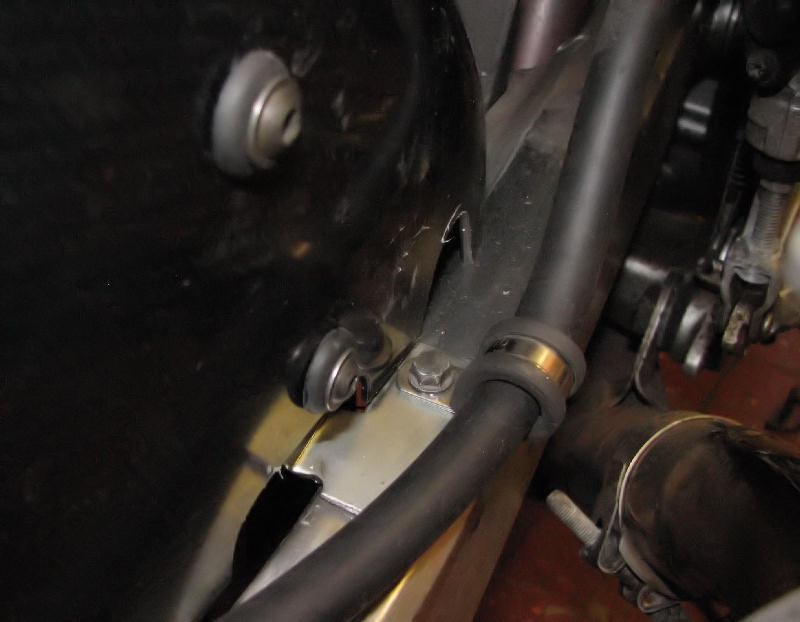
Hugger and bracket were then fitted. I also removed the original bracket, which was looking furry and fitted a stainless steel P clamp as shown. Enough for the first weekend. |
|
|
The following week. |
|
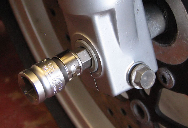
| The following weekend, Started on the front-end. I managed to buy a 12mm hex key for the front axle, so the first job was to remove the front wheel. The hex socket is a Draper item and comes with a number of size bits, very useful. |
|
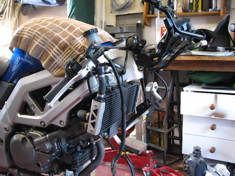
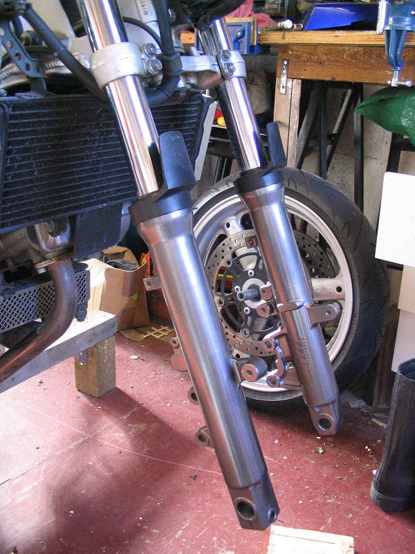
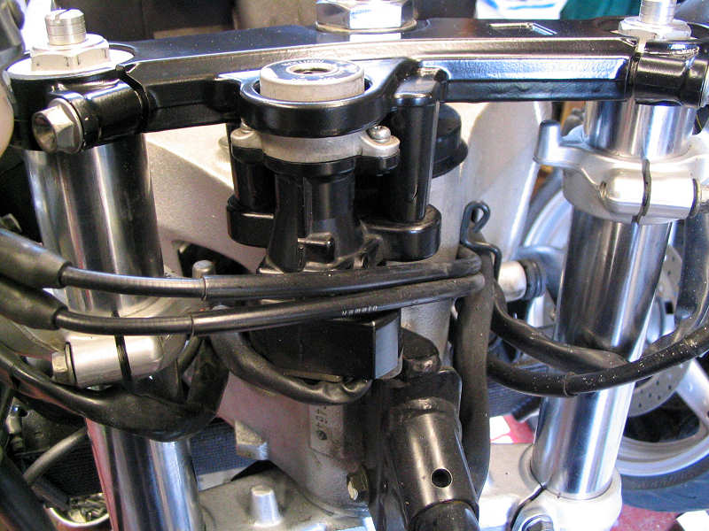
| I then stripped the entire front end and was left with this. It's not as complicated as it looks, but scares the life out of my wife. |
|
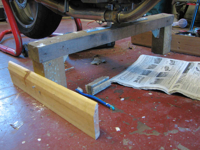
| In case you wondering what's holding the bike up. It's the patented 'fence post stand' that got mangled when my old SV got knocked over in July 2005. I've fitted new L brackets and it now has out-riggers to stop the bike rolling off if nudged. More details here |
|
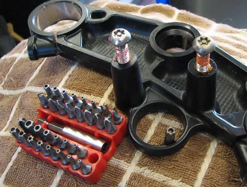
| Removing the top yoke was easy enough except when it came to removing the ignition lock. This is held in place with two special security bolts, basically a Torx bolt with a pin in the middle. I had a set of security sockets already (this set cost about £5) so it was just a case of applying elbow grease as these bolts also have loads of locktite on them. |
|
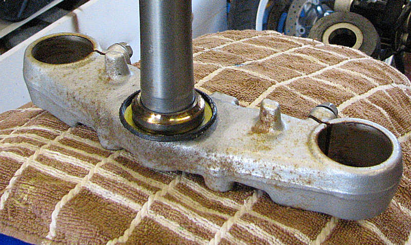
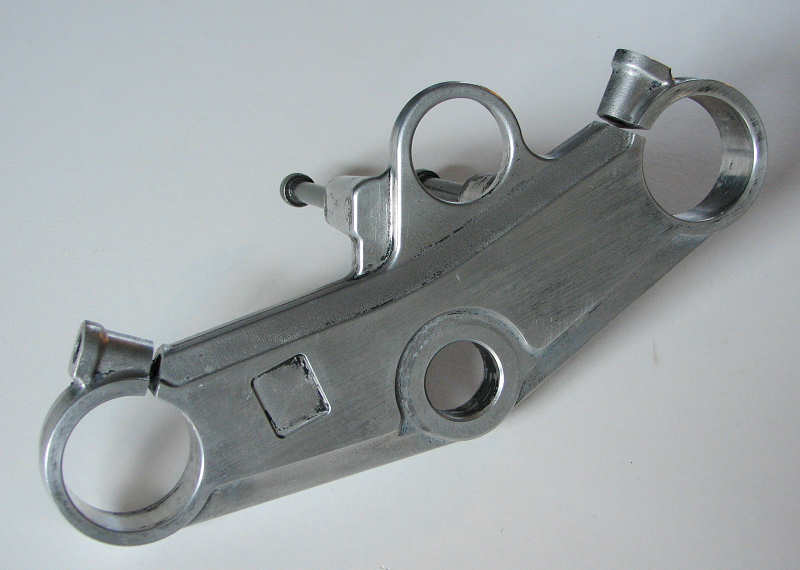
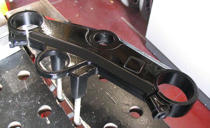
| The reason for stripping was to get at the bottom yoke and introduce it to the concept of a decent coat of paint. |
|
| A good wire brushing and cleaning with a Dremel gave me a good base to apply some coats of smooth Hammerite |
|
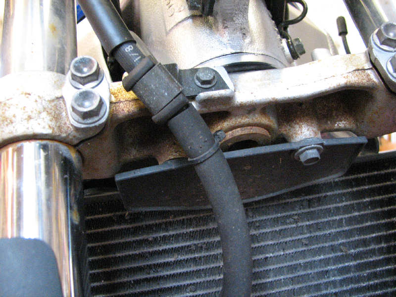
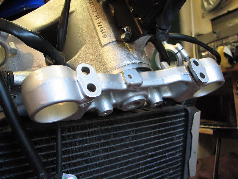
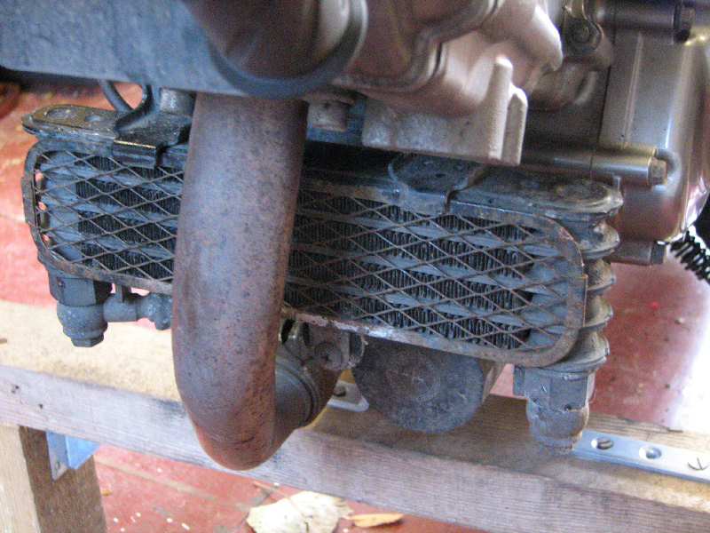
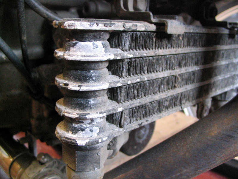
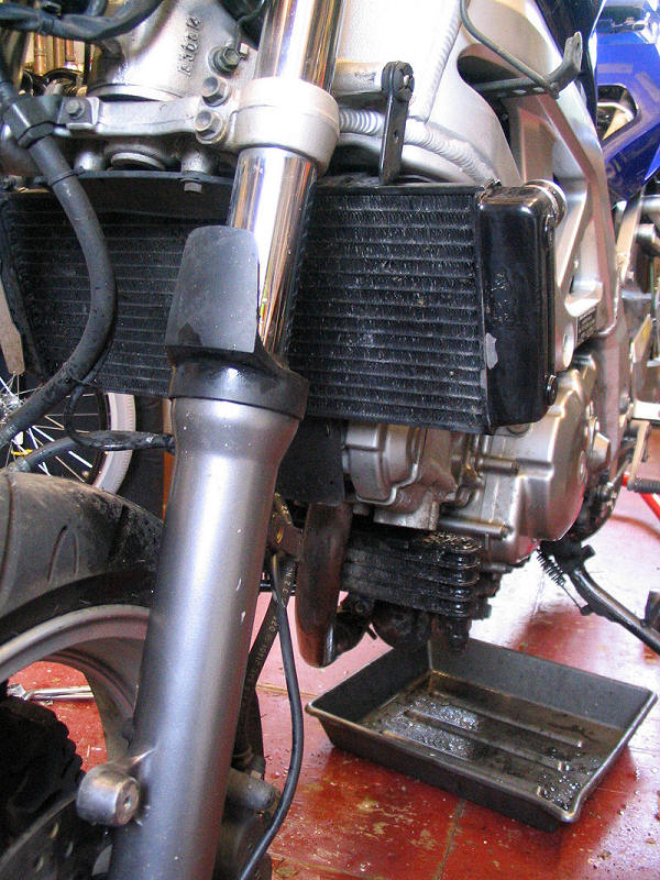
| Whilst the forks where missing, it gave me a chance to look at the state of the oil cooler and exhaust header. Not a pretty site. |
|
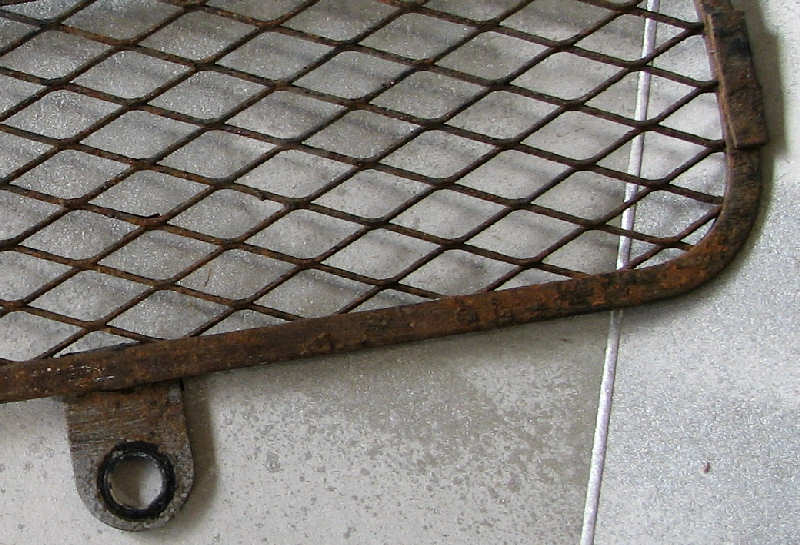
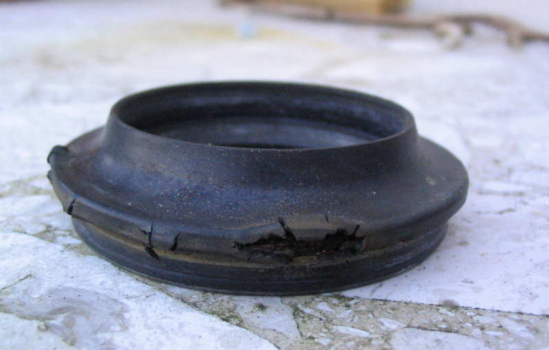
| The oil rad cover was pretty trashed as you can see. I've bought a stainless steel item from Beowulf to replace it at £22.50. I did prefer the Hamicad version, as this wraps around the sides, but this is only sold together with the water rad cover at around £79, which was too rich for me. |
|
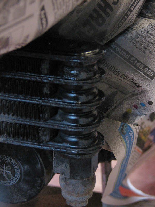
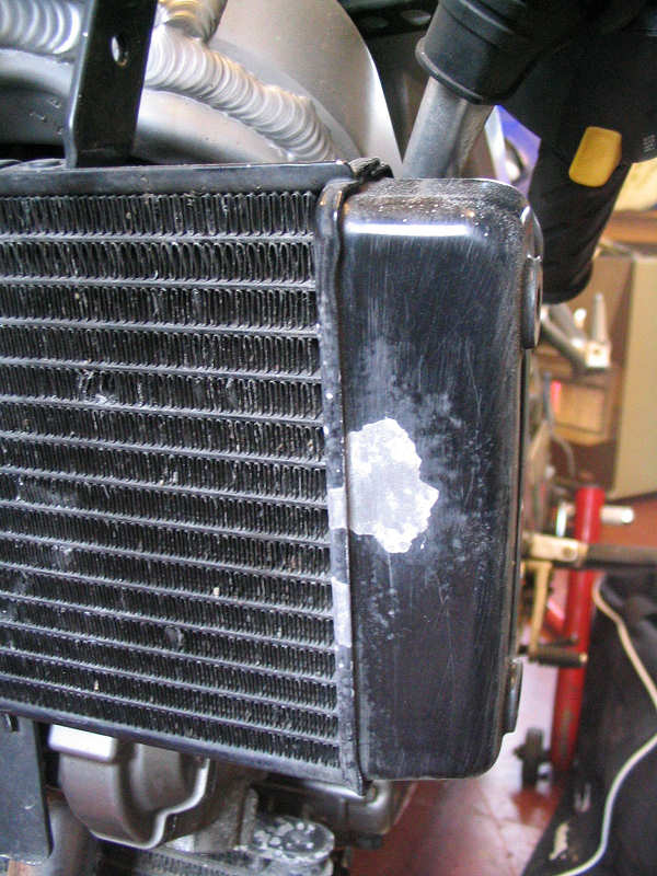
| The left side of the oil rad was also suffering, paint was peeling and bubbling, so another attack with the Dremel and a quick touch up spray with PJ1 engine paint improved things. At some point in the future the whole lot will have to be replaced, perhaps with a nice Earl item? |
|
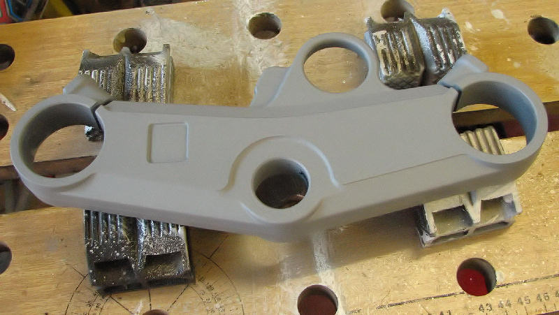
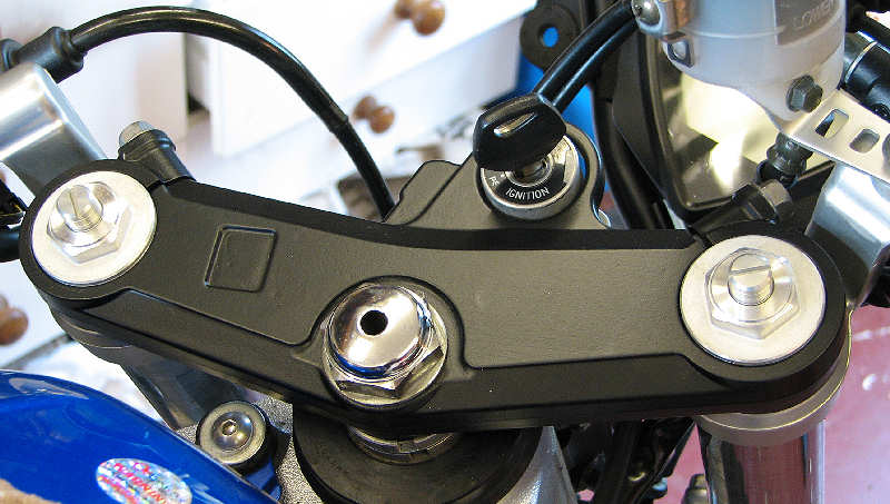
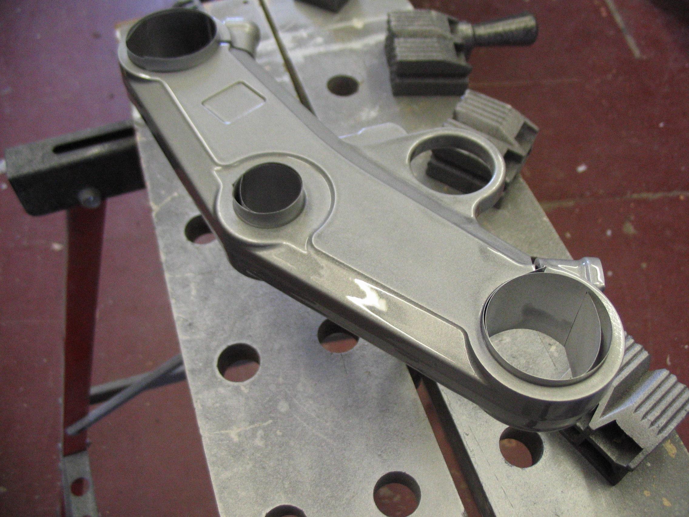
| The top york needed a tidy up too. The paint was scuffed around the ignition lock and elsewhere. I tried just a quick coverup coat of satin black acrylic but it didn't take properly, so I had to strip to bare metal and repaint. |
|
| Prising out the badge mangled it a bit, so a new one is on order, but this looks tidier. |
|
|
|
|
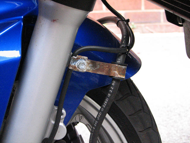
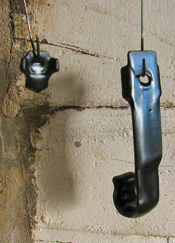
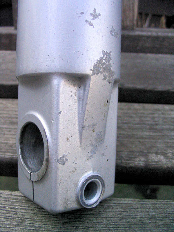
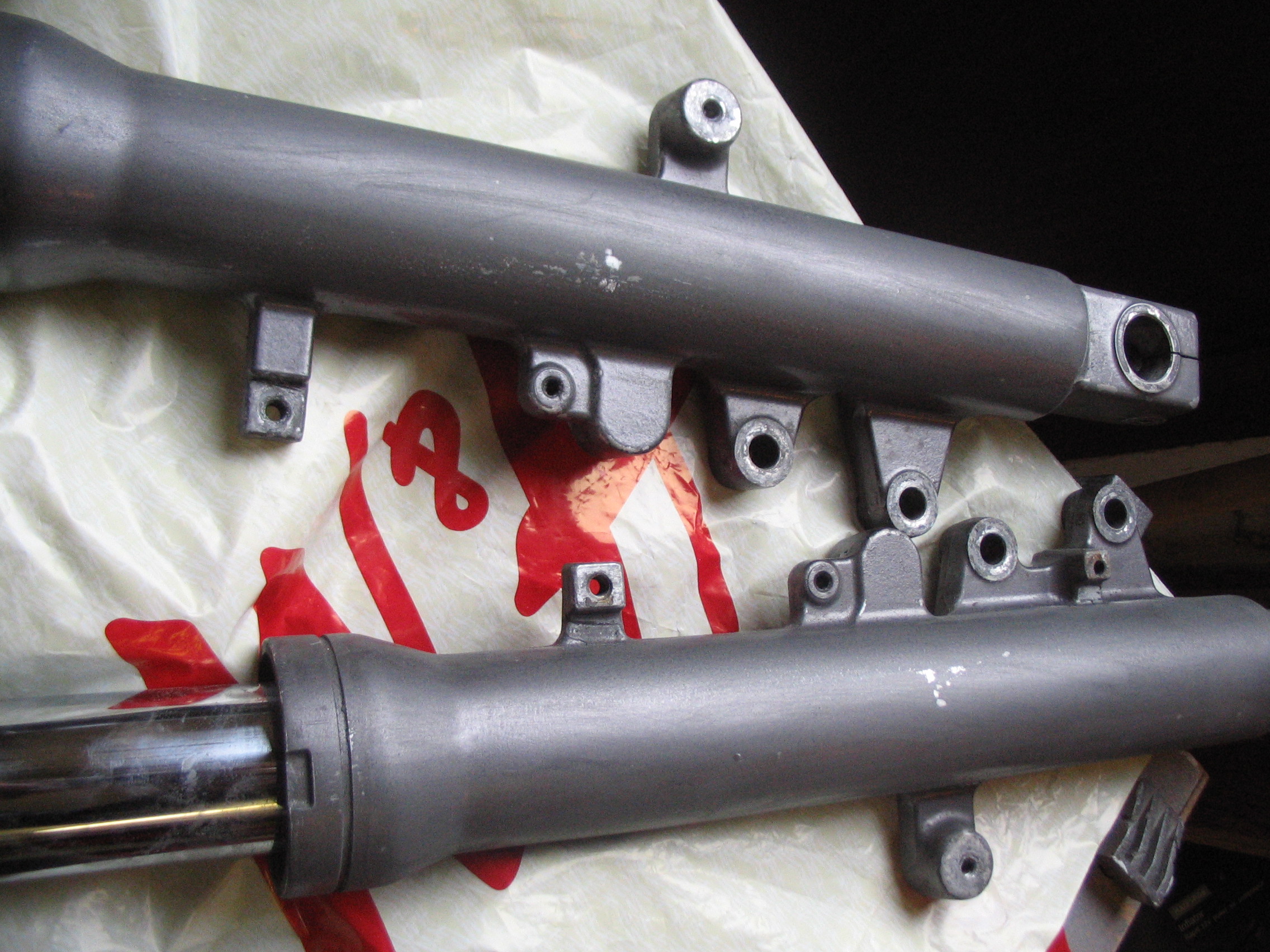
| The next bit of rot to deal with was the small brackets on the left fork leg. This is how the looked in October when I got the bike. |
|
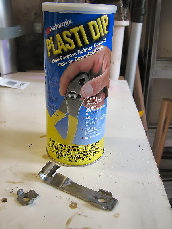
| I could have sprayed them with silver Hammerite, but I decided to use a different approach this time. I bought a tin of plastic dip from Frosts restorers. Just clean up the parts to be coated and dip. Sounded ideal. Note the cleaned parts in the foreground. |
|
| Seemed simple enough despite the bad Italian to English instructions. I used a thin wire paperclip to hold the items and just slowly lowered them into the paint tin and slowly removed. Allowed them to drip and then left them to dry. The paint has the consistency of tar so one dip was enough. You can see in this shot that the hole has filled. Once dry the thickness of the coat seen here does reduce a lot. A second experiment using a cotton thread was better, just stretch the thread tight horizontally to ensure minimum contact. Don't try and remove the thread just cut it close the to item. |
|
| The next day I tried to remove the wire. This proved tricky as it was well attached. I had to use a sharp blade to cut it away. If I'd just pulled then the coating would have ripped. I then opened up the hole using the tip of an soldering iron. This made the hole bigger without exposing metal. I then placed back on the bike with some stainless steel button screws. |
|
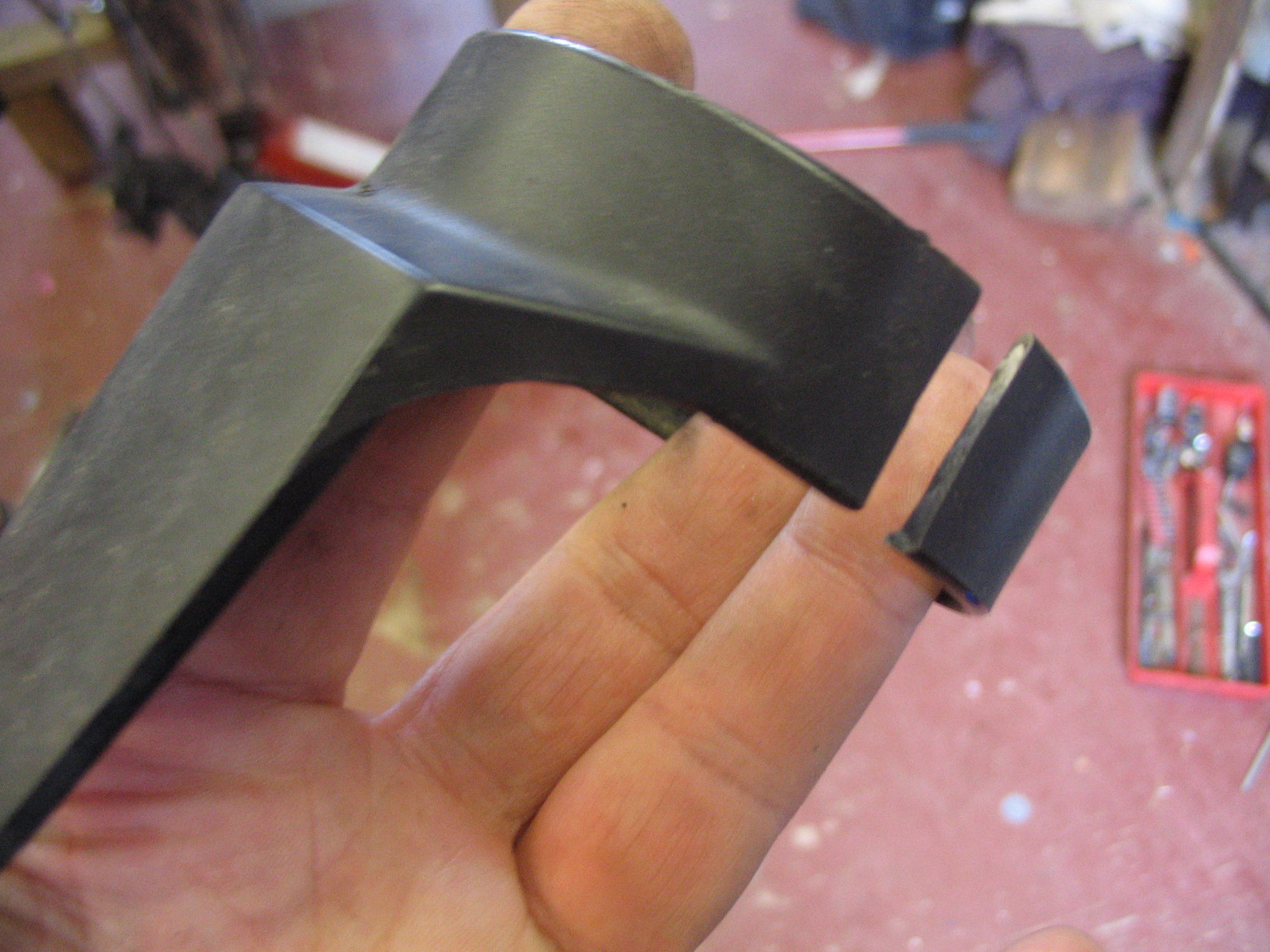
| The finish is not as refined as a good coat of paint, but it looks neat enough. The coating feels more like a rubber than plastic, so should take knocks in it's stride. We'll see how it lasts. |
|
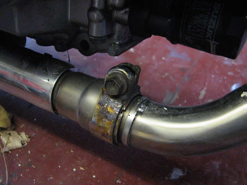
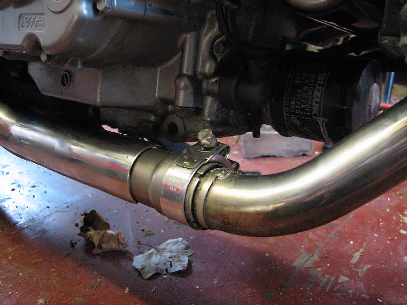
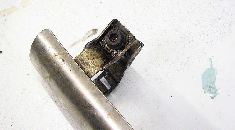
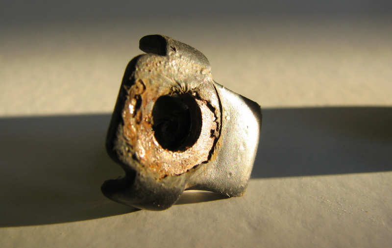
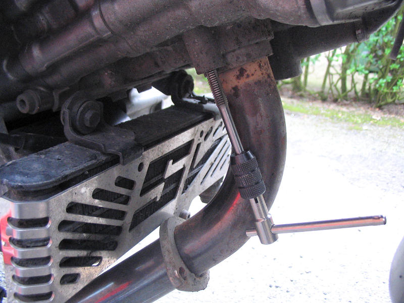
| Just like my Mk1 SV the front exhaust clamp is made of crap metal. I have a spare Mikalor that will fit this nicely. The pipe is 45mm so order the 43-47 item, mine is the marine grade item. Still spotless on my mk1 SV. |
|
| That's better. The pipe has a small lug on the underside that locates the old bracket in position. I filed that off and fitted the Mikalor. Whilst sat in front of the pipe, I removed the two hex bolts clamping the pipe to the header. They were stiff and corroded as I expected. I had to re-tap the thread (to clean it up) and then replaced the bolts after a good spray of antiseize. |
|
| I also remove the cosmetic exhaust plate as I suspect that too would be corroded. The plate itself wasn't too bad but the screws were rotting away. I cleaned up the plate and threw away the screws in favour of stainless steel items. |
|
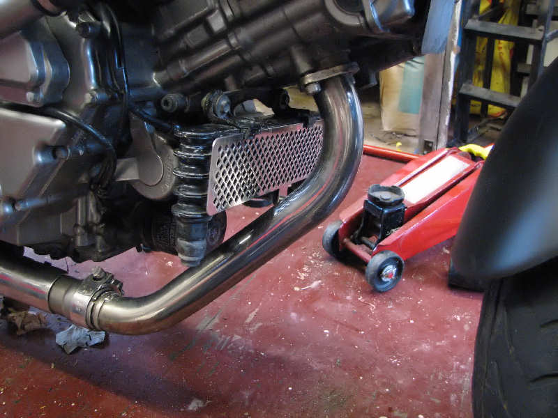
| I then attacked the brown header pipe with Solvol Autosol and some fine wire wool. It's not perfect, but it a darn sight better than it was. Note the fender extender and the oil rad cover (also attached with a stainless steel screw. |
|
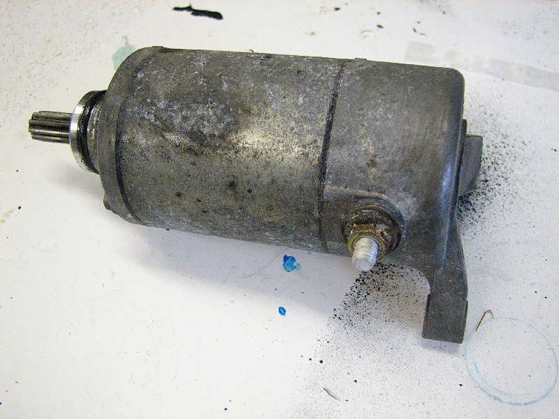
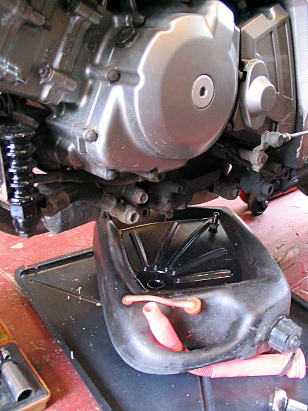
| At this point I took a look at the electrical connections for the starter motor and oil pressure switch. The oil pressure switch was fine, but I still coated it in grease before replacing the protective rubber boot. I can't say the same for the starter motor. Some rust and white powdery corrosion was evident. So I took the motor out. Easy enough to do, just remove the two bolts and the electrical connection and give a very gentle tap from the other side. Care must be taken not to break the thin wire going to the oil pressure switch. You will loose a bit of oil so has a drip tray handy. |
|
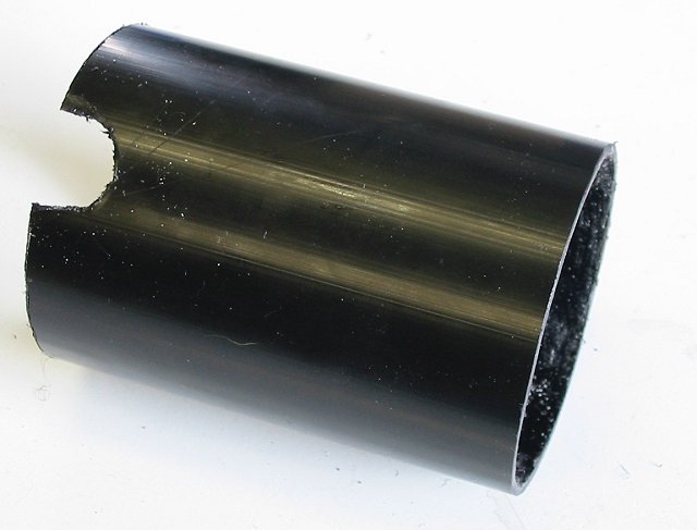
| As you can see the motor was is a poor state, so I cleaned it up and produced another of my home made devices, a starter motor cover, made from a plastic drain pipe. I've had this fitted to my mk1 SV for 5 years or so and it makes cleaning a breeze and can cope with the heat from the engine. See Diary of a MK1 SV Restorer for details |
|
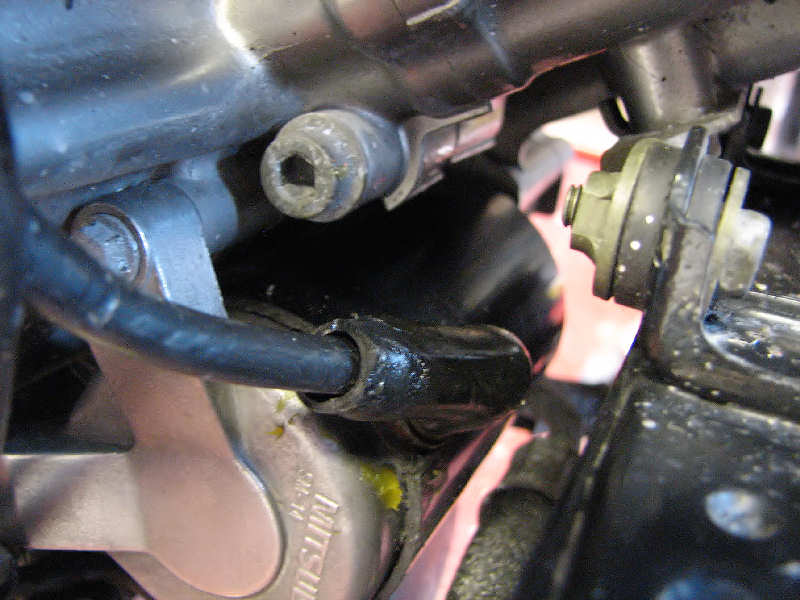
| The motor was then replaced, screws coated in antiseize and electrical connections greased. The boot covering this connection is very poor compared to the MK1 SV, maybe I'll buy one of those and replace it. I'll clean the grease off later. |
|
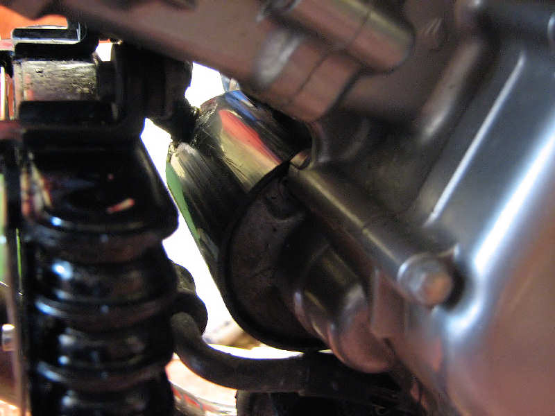
| It's not so obvious as on the MK1 SV but it'll give some protection from the elements. |
|
|
The following week. |
|
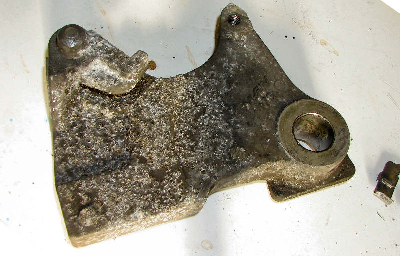
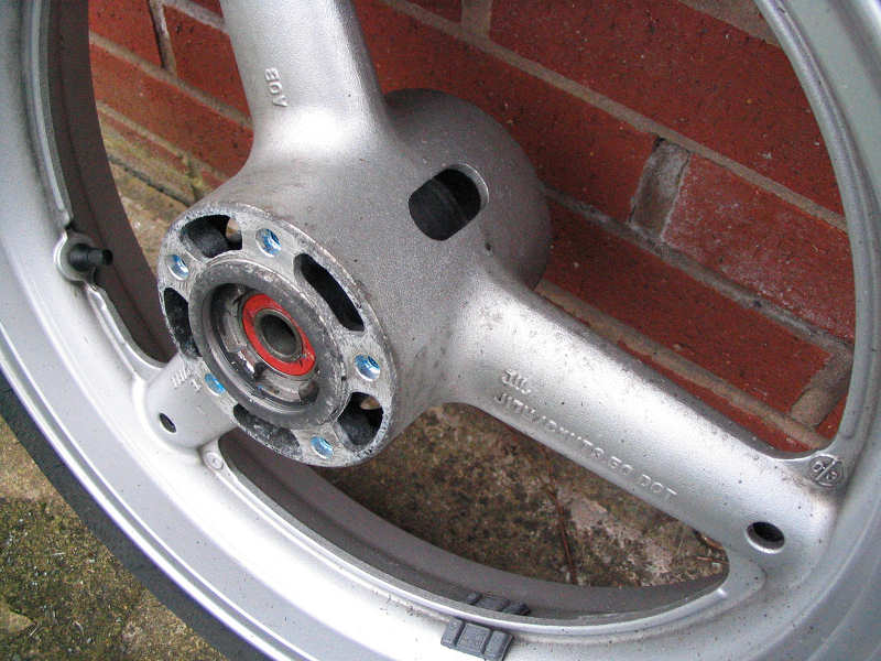
| Time to turn my attention to the other end of the bike. I'd already noticed that the brake carrier was looking furry. Removing the rear wheel confirmed the rot. |
|
| There's no point in polishing this item. It's pain to get at once back on the bike and it would just return to this state in no time. So I removed the dirt and grease and then used a wire brush to get back to clean bright metal. Then a few coats of smooth silver Hammerite. A big improvement. |
|
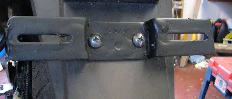
| For some reason, probably to get back access to the rear wheel, I removed the number plate and noted the rust on the carrier underneath. Again I took this down to bare metal. I did think of painting it with black Hammerite but decided instead to use the plastic dip. I knew I wouldn't get as good as finish but as it's manly hidden from view and I thought the plastic coat would last a lot longer. |
|
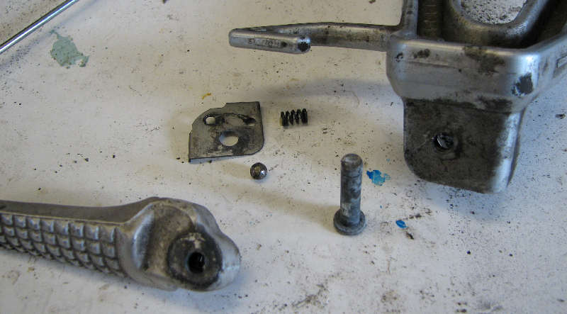
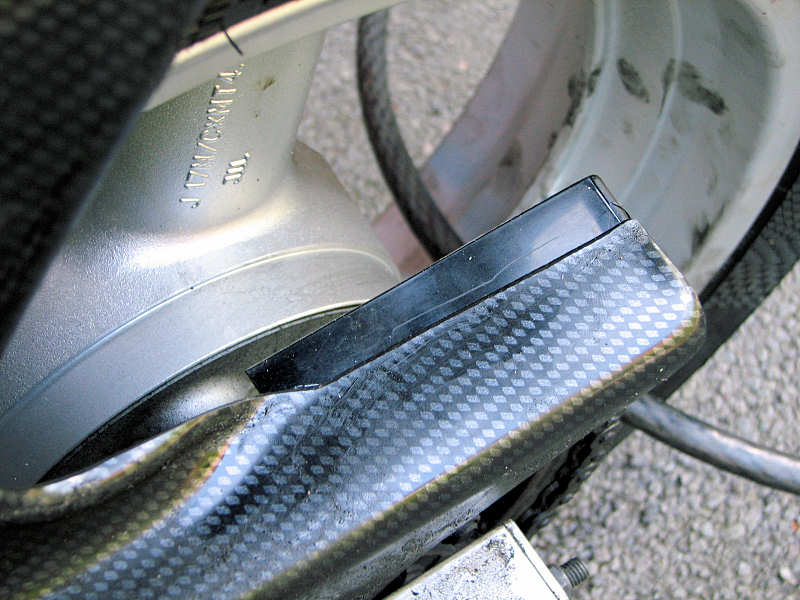
| The rear footpegs are another area where corrosion sets in. These used to stick and jam on the old SV, plus the pin in the middle rusts along with the circlip. So a good strip down and clean. The ball bearing and spring were covered in grease. The peg was reassembled and the centre pin was coated in anti-seize. I use both copperslip and Mr Fastner anti-seize when working. In this case I used the Mr fastner version which is a spray on aluminium based product. Goes on like silver grey paint. Is doesn't dry completely, but being silver blends in with the rest of the footpegs. The main use for this type of anti-seize is when applying stainless steel bolts into an aluminium casting. You could use copperslip to stop the corrosion, but the copper reacts with the aluminium and stainless steel with an electrolytic effect. |
|
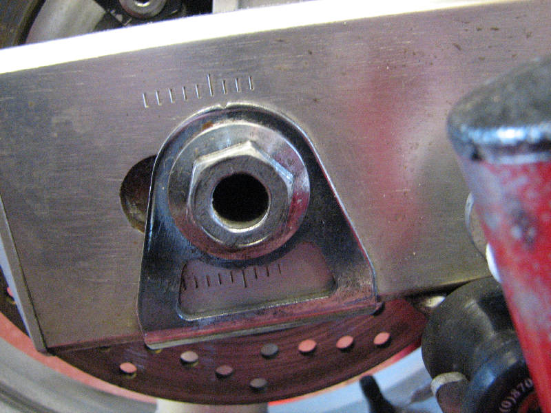
| The rear axle bolt and side plates were looking shabby too. So I dug out the wire wool and then the polishing kit to at least put a bit of a shine back on things. Here's a before and after shot. |
|
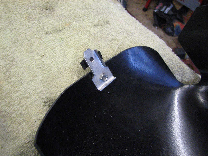
| I've already mentioned that the hugger was intended for a naked SV. I think it was also designed for the '03 model as the tool box is very close to the hugger. I've improved things slightly buy adding this small lug to the back of the hugger. This pushes the plastic in by a few mm giving a better clearance. |
|
| Another shot here |
|
| Time to start putting things back together again. Brake carrier. The rear caliper was cleaned and greased. The banjo fittings were corroded, so these were cleaned up with a Dremel and wire brush. They were then painted with clear nail varnish to project them |
|
| Number plate carrier. Finish isn't great but it ain't going to rot no more. |
|
| Axle head and side plate. Also coated in clear nail varnish. |
|
| At this point I dragged the bike back into the drive. Looks quite cool with the cut-off exhaust. |
|
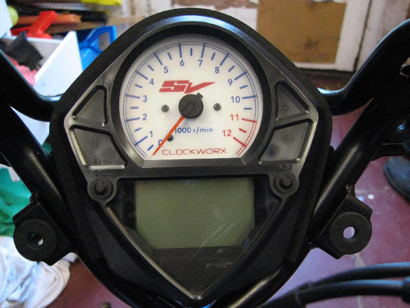
| A night time shot of the new clock face. |
|
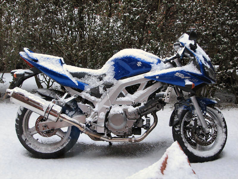
| And the next day it did this. Blasted weather. |
|
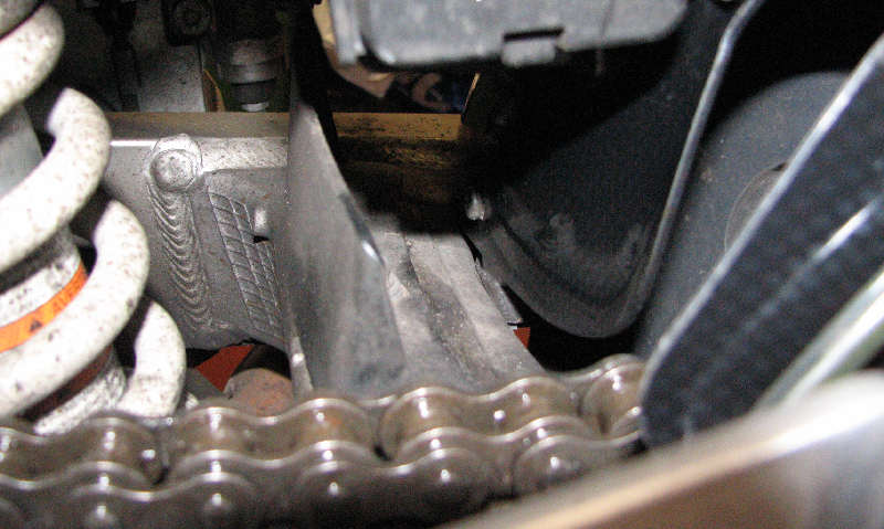
| Later that year, I noticed while fitting the tyre that the hugger is doing a pretty poor job of keeping chain oil off the underside of the bodywork. You can soon see why when you look straight down from the pillion seat, the guard doesn't extend far enough over the chain. I've since added an extension piece made out of an old DVD case and glued into place. Another top bodge. |
|
| That's about it for this year. I have ordered some more Milalor clamps for the end can. The bolts were rusting and was clear that these were the cheaper version (w2). The replacements will be marine quality (w4) and completely stainless. | |
|
Winter 2006 -2007
|
|
| The lovely respray I did on the top yoke last year didn't last long, in fact I noticed a small chip within weeks of completing. Because of this I didn't fit the new badge. The paint gradually flaked, especially around the stem bolt and looked a right mess in the end. So here's a shot of it after the paint stripper got it. |
|
|
Next job was the front brakes. I gave them a mid year service
in the summer and noticed that one piston was reluctant to move on the left
hand caliper. It wasn't jammed but there did seem more resistance. This was
combined with a feeling that the brakes were a bit wooden, still had plenty
of power but lacked feeling. I decided it was a job that could wait until
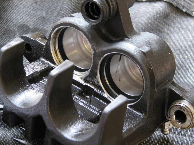
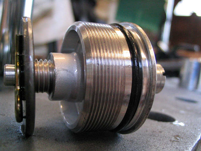
the winter hibernation. So here we are in winter. This is not a job I relish. Servicing brakes is a serious business, so do not read this as a comprehensive guide, proceed at your own risk. I removed the brake pipes and let the fluid drain into a container. I then removed the calipers. I use compressed air to remove the pistons. I do this with a normal car foot pump. Most foot pumps come with a cone shaped adapter for using on inflatables. I just cut this a bit shorter and screw it into the opening where the brake pipe connects. I then attach a foot pump and pump. This is a little trickier on calipers with twin pistons. One piston will pop out before the other if you're not careful. I found that laying a small spanner inside the caliper lets the pistons move out almost completely, so if one moves easily it can only go so far without popping out and releasing the air pressure. The other will eventually move (unless you're unlucky). Once they're both level with the spanner, remove it and a you can either pull them out by hand or a final pump should see them fly out. BE WARNED they can come out with a bang, especially if they are sticking.
|
|
|
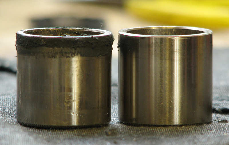
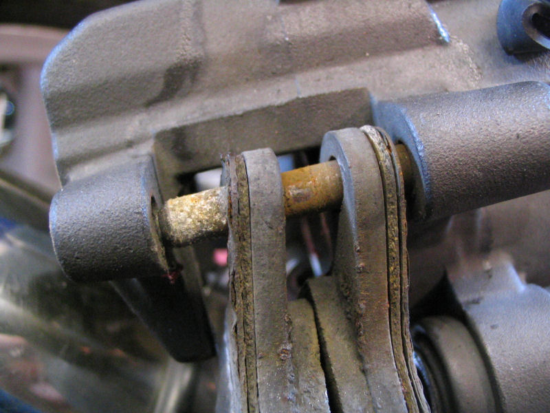
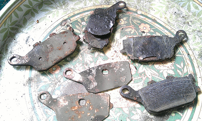
You can see in this photo a before and after photo of the
pistons. You can see the accumulated muck on the top of the piston that is
exposed. In this case it's mainly rubber grease and dirt and is easily
removed. If you have corrosion, buy new pistons. In the caliper photo. you can see the piston chambers. These should be nice and clean. There are two rubber rings inserted. The outmost one, is a dust seal, the inner the main fluid seal. In the photo you can see that the dust seal is removed in the chamber furthest away. You need to check that the dust seal is in good order and that the metal between the dust seal and fluid seal is free from corrosion. If there is some corrosion, then remove both seals and remove the corrosion with some wire wool but be careful! In my case there was no corrosion and the seals looked in good order, I just gave them a good clean with a brake cleaning fluid and replaced. If you have any doubts then buy new items. I then coated the pistons in clean brake fluid and re-inserted them. Rubber grease was then coated on the exposed part of the pistons, pads inserted and the retaining pin cleaned and coated in copper-slip. The calipers refitted and new brake fluid used and system bled. |
|
| Next job was to dismantle the forks so I could replace the oil. Had a lot of trouble removing the small screws that clamp the speedo cable and brake pipe. Looks like I forgot to squirt some anti-seize on them before installing and some corrosion crept in. It took a Dremel tool to cut a cross head slot into this allen headed bolt and then a few healthy thumps from an impact driver to get the thing out. |
|
| One year on after last years experiment with plastic coating. A resounding success I think, still looks good. The small pock marks are the downside to this process, but you only seem them up real close. |
|
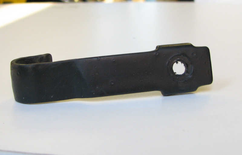
| The smaller clip suffered somewhat when I had to remove the stuck screw mentioned above. |
|
| The painted forks on the mk2 seem to fair far better than the lacquered mk1 forks. Although you can see some damage in this photo and the one below. |
|
| I don't consider them bad enough to strip and repaint this year. |
|
|
The following weekend I re-assembled the front
end and re-bleed the brakes. I tried to re-dip the fixture shown
just above using 'Plasti-dip'. The problem I had is that the plastic dip has
gone a little thick over the year and was the consistancy of thick tar.
Apparently you can thin it with Nahptha, but that's a little hard to come
by, so I went back to Frosts restorers
and bought some dedicated thinners. The part was dipped and left to cure.
|
|
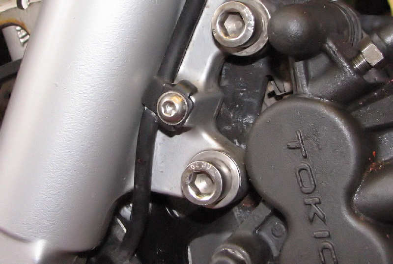
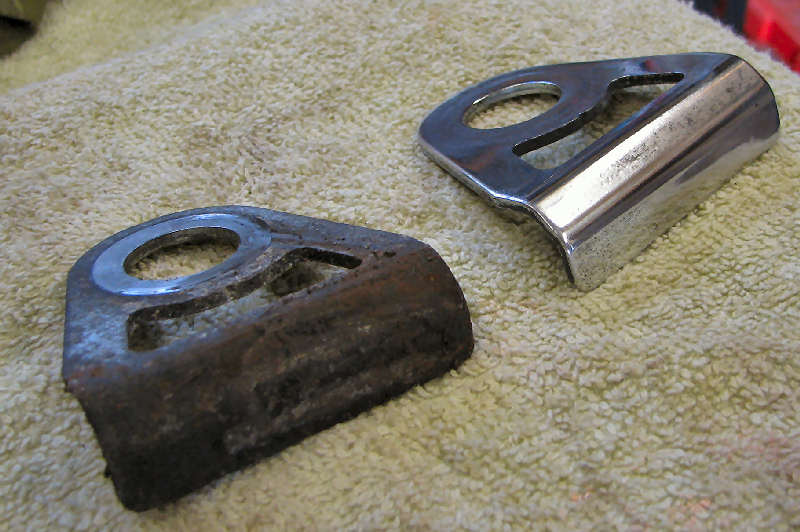
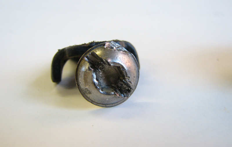
| The weekend after I looked at the back end of the bike and gave the rear brake caliper a service. Not a lot wrong, just gave it a good clean and flushed some new brake fluid through. I then took the bike outside to give it a good clean. I'd already stripped the paint off the footrest guards and simply polished using some Solvol. They looked a lot better all ready. I decided to remove the bolts in the right hand guard to get into their recesses for further cleaning polishing. These bolts hold on the rear brake cylinder. Top one came all right but the lower was stuck and the allen head soon rounded off. I had to drill the top off the bolt, as you can see in this photo. I then had to remove the shank of the bolt from the cylinder itself. A pair of molegrips managed to budge it eventually. |
|
| I found some spare stainless steel screws to temporarily replace the originals, not pretty but they'll do until I order something better. It's hard to see the polished finish in these photos. It's not up to chrome level, but it looks nice and should be easy to keep this way. |
|
| The other side looks nice too. That's as far as I've got, what with the interruptions of my sons football and the constant rain showers. Next job is the the front exhaust down pipe is a nice shade of brown. |
|
|
Winter 2007-2008
|
|
|
I didn't get the SV in the garage until mid
January this year. This was partly due to the mid weather and my reluctance
to get stuck into some of the jobs that awaited me. Procrastination! I knew
that there wasn't a lot to do this year, so I shouldn't have been so lazy.
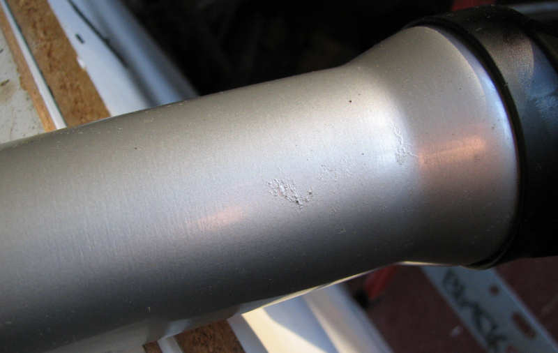
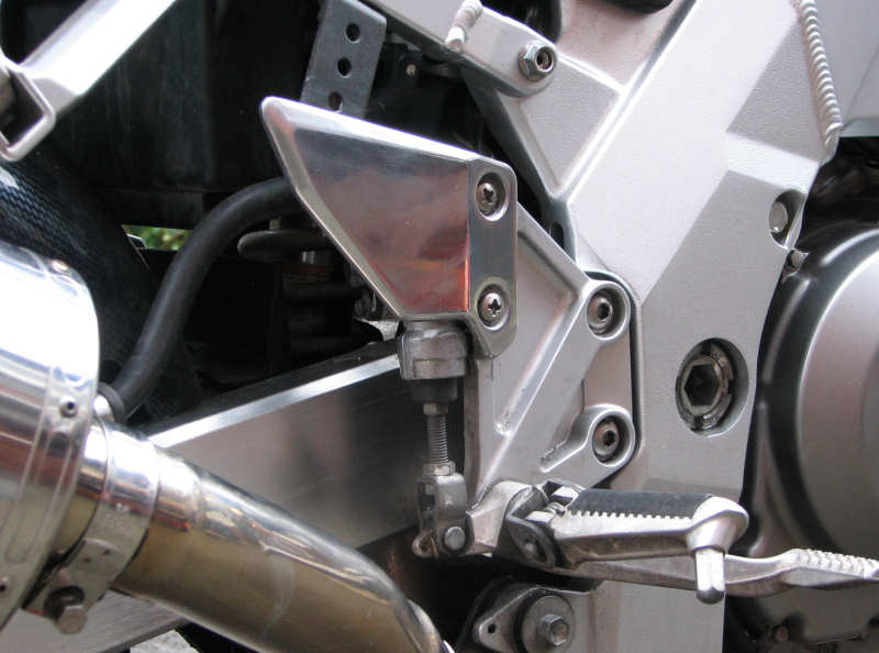
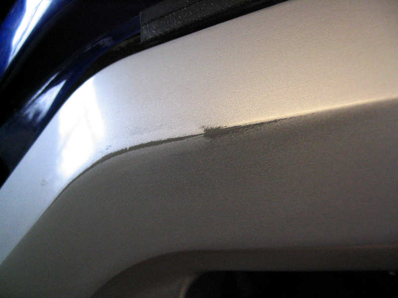
The biggest blot on the landscape was the paint wearing off the frame. The
paint is incredibly thin in this area so it doesn't take much effort to
remove. When I first noticed this blemish I was quite taken aback. I not
aware of my leg rubbing this area but I can't think of any other explanation
of it. Re-spraying a section of the frame didn't bother me overly except
that I know that silver comes in many different shades. None of the major
bike paint suppliers could help and it's not listed by Suzuki either.
Anyone who's read these artilces before will know favourite silver paint is
smooth Hammerite, but it was obvious that this would not be a good match. I
didn't plan to spray the entire frame so a good match was important. I took
a few trips to Halfords and bought various silvers that looked close. I
sprayed spare bits of metal and placed them on the frame to compare
with the original colour. I found that Halfords Aluminium Silver was the
closest match (or so I thought).
|
|
|
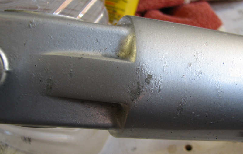
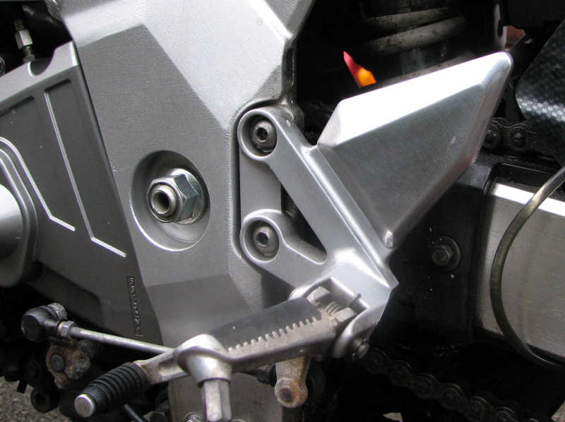
First job is preparation. Some light rubbing
with wet and dry made the frame look worse but you need something for the
paint to grip to. If you have to apply fresh paint to an existing colour
it's best to find some boundary for one to finish and the other to start.
Car sprayers usually spray an entire panel for this reason. I decided to
spray between the welds on the headstock and swingarm mount. Where the top
beam joins the lower beam I masked up to corner where the the change of
angle would hide the change of tone. I also planned to 'feather' in the
transition to blend one colour to the next rather than have a hard line, so
I lifted the masking tape in those areas a few mm.
|
|
|
It's not a good idea to spray in low
temperatures. I have a butane heater in my garage so that got fired up
beforehand and all paint aerosols were placed in a bowl of hot water for 20
minutes or so. Work progressed well and the frame was looking good after a
number of coats. I then peeled back a bit of masking tape to reveal that not
all was well. I can't say with hand on heart that the match looked as
good as it did with the test piece. The aluminium colour was a bit too grey,
so that had to go. Time for some more testing. I eventually settled on
Ford Stratos Silver. It's pretty good, probably about 99% and you'd be hard
pushed to notice any difference from the untouched parts of the frame.
I left this a few days to harden and then used some rubbing compound to give
a smoother more polished look. I did consider using some clear lacquer to
add further protection but I thought this would look odd as it would give
the frame a glazed look, which the rest of the frame doesn't have.
|
|
| Next area for attention was the forks. One dust seal had cracked and the internal metal spring was leaking rust. Easy and cheap job to fix, so I ordered some new seal. |
|
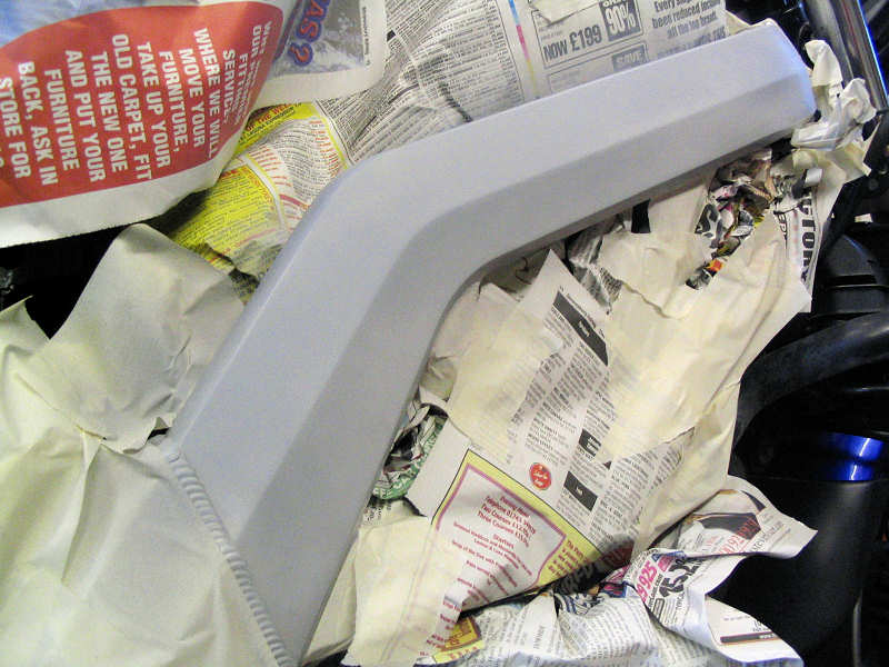
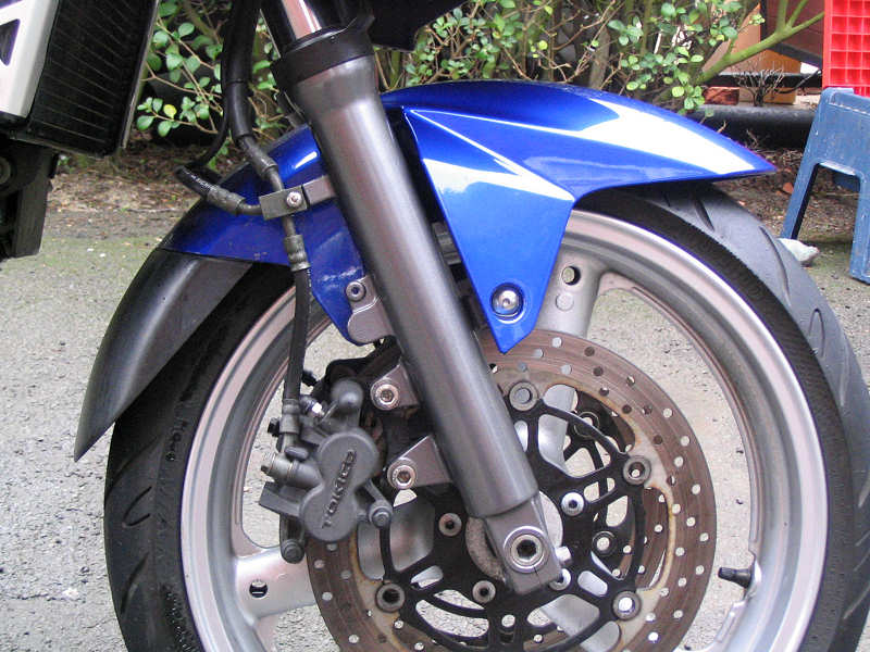
| Whilst stripping things down. I noticed that the pitting on the forks had got a lot worse over the last year. Should I re-spray or strip and polish? I chose re-spray. The forks are a another shade of silver from the frame and wheels. I did consider Hammrite again but decided that the same colour as the frame would be fine. |
|
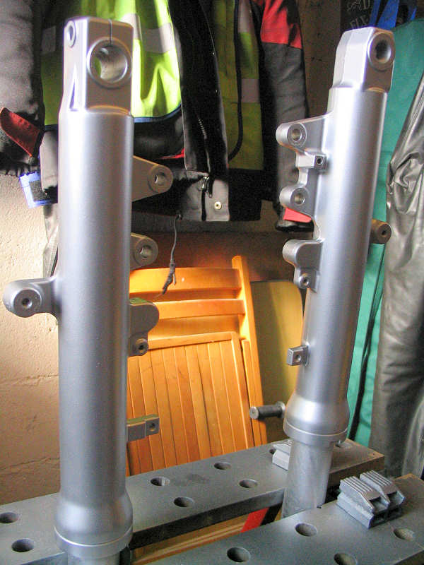
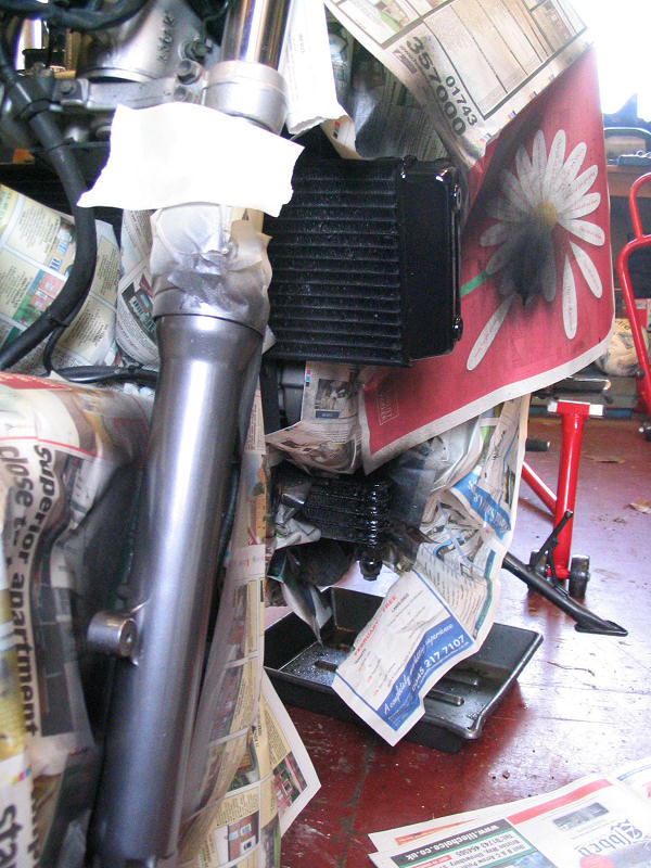
| The forks were rubbed down, cleaned to remove any grease or oil. Dust seals and guards were removed too. Newspaper was wrapped about the legs to keep paint to the areas I wanted. Primer was applied and the a good few coats of Ford Stratos. Again I wasn't happy with the result. Far brighter than the original silver and a bit to 'blingy' for me. I decided that I'd like the forks the same colour as the engine, a grey-silver, so back to Halfords... |
|
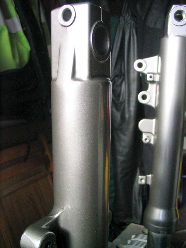
| This is Vauxhall Steel Grey. A bit darker that I intended but I like it. I've since noticed that most of the Hondas in the bike shop next to my office have grey fork legs, so I'm not a trend setter after all. |
|
| Whilst I was at it, I gave the top yoke a quick blast of paint too. I used Hamerite satin black for this. Looks horrible in this photo as the paint was still wet when I took it. |
|
| Time to re-assemble |
|
| A close up of the finished item |
|
| Work Completed. Except for a damn good clean and a polish. I need to get some wet n dry on that down pipe too. |
|
|
Winter 2008-2009
|
|
| Got started a bit later this year. Can't say I enjoy this task as much as I used to. It all very well saving the tasks until the winter period when it's too unpleasant to ride, but it does mean you have to do a lot of work in an short period. It doesn't help that I seem to be doing the same jobs every year. | |
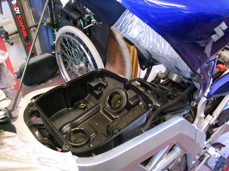
| I started as usual by pulling off all the fairing and bar weights. It makes it a little easier to get through the workshop door, which the same width as a normal street door. I then stripped off the petrol tank and seats. I didn't realise that the fuel line was a quick release job. Squeeze two little buttons on the end of the hose and off it pops. I had far more hassle with the electrical connector which had no slack on the cable and was tucked way where I could only get one hand to it. The first big job was to check the valve clearance. The bike has now covered 18k miles and it should have been done back in the summer. Getting to the rear cylinder was easier enough and so was checking the valves one I found my metric feeler gauges. Exhaust gaps were fine but the inlet only were tight but not enough to adjust |
|
|
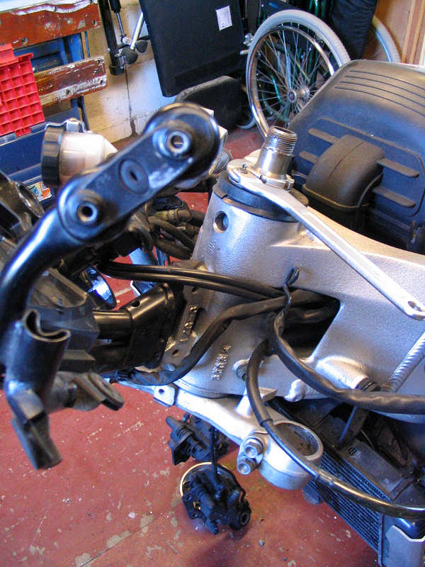
Next job was to strip the front end down. The
paint on the forks hadn't suffered to well in the last 12 months and nor had
the top yoke. I don't know why but for some reason I cannot get paint to
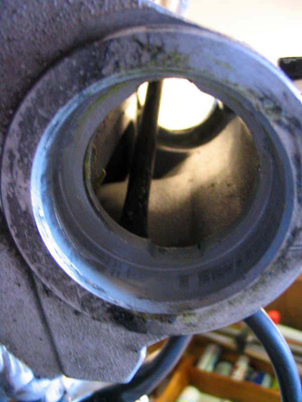
stick to the aluminium on this bike, even with Hammerite. I had done some research on this and I've sent away for some etching primer which I hope might stay on the metal. Meantime it's a soak in Nitro-Mors to get back to bear metal so I can start again. I took this shot just to show that it's worthwhile buying a proper C- spanner as shown, for removing the castellated nuts shown. Back in June, the bike had an MOT and the tester mentioned a couple of things that needed attention. One was the head bearings. The tester thought they were a bit notchy. Now I had the bike with the both wheels in the air, it gave me the chance to feel the steering without any friction from the road. It felt okay to me until I had both fork legs removed and then I tried again. I could now feel a roughness. I removed the steering stem and inspected the bearing race for wear. I couldn't see any. It did strike me though that the steering was overly tight though. |
|
|
So I put it back together again with just enough
tightness to ensure to slop and tried the steering again. This time I could
feel no roughness. When head bearings go, they tend to affect the bottom
race worse, as that's where all the weight of the bike it concentrated. With
round bearings like this they tend to leave pot holes in the race, rather
than wearing a nice consistent grove. The effect of the pot holing is
to give the steering a notchy feel, a subtle click, click, click as you turn
the stem. It's this that screws up the handling. When the notchiness is
really bad, it has an affect on the handling not unlike a flat rear tyre. As
you tip into a corner the bike feels like its over steering or like the back
is about to step out. This is down to a slight amount of oversteer as the
head bearings won't move to the position you or the bike wants, instead
moving from one pit hole to the next. I hope that makes some sense.
I'll leave the existing bearings in place for now. I'll repack with grease and pay more attention to the pressure on the bearings than I did last time I took this apart. |
|
|
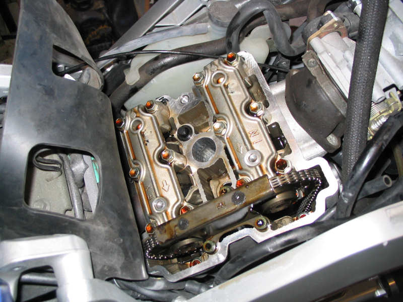
The next day was spent checking the front
cylinder valves now that I had clear access. It's still a pain to get to
them though with the rad in the way. I disconnected the rad at the bottom
and swung it away from the cylinder as far as it would allow and then tied
it in place to the front subframe. Again the inlet valves were near to the
tighter end of the tolerance allowed. I then broke open the Nitro-Mors and attacked the forks and top yoke. I called it a day that that point. There's always next weekend. |
|
|
The following week |
|
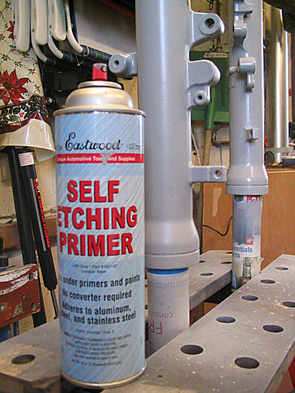
| Sorry no photos of forks being attacked with Nitro-Mors, it's a bit tricky taking photos and handling this nasty stuff at the same time. Anyhow I'm sure you've seen forks without paint on before. Here's a photo of the freshly primed forks and the magic primer, which I hope it going to work better than the previous stuff. |
 |
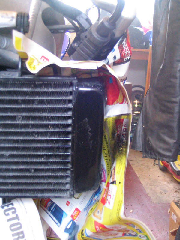
| While that lot was drying I thought I'd have a look at the radiators now that I have clear and uncluttered access. As you can see the oil rad is suffering. |
 |
| As it the coolant rad. So a quick rub down and I'll deal with both with some PJ1 Engine paint, which seems to stick on quite well and doesn't need primer. |
 |
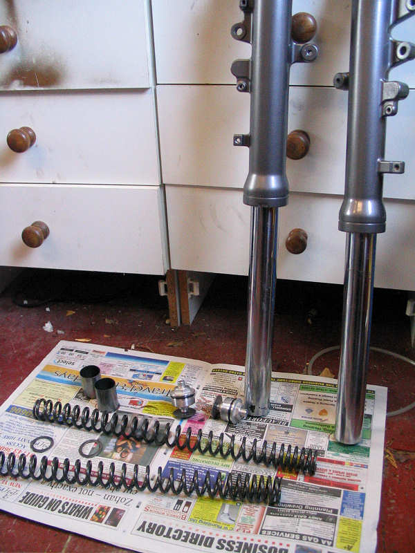
| It occurred to me at this point that the fork oil could be due for replacement. I checked my service logs and guess what, it's overdue. So as they were off, time to tip out the oil. Note the new shiny metallic grey paint. As you can see a few other bits few out besides the oil. I left the the forks to drain over night. |
 |
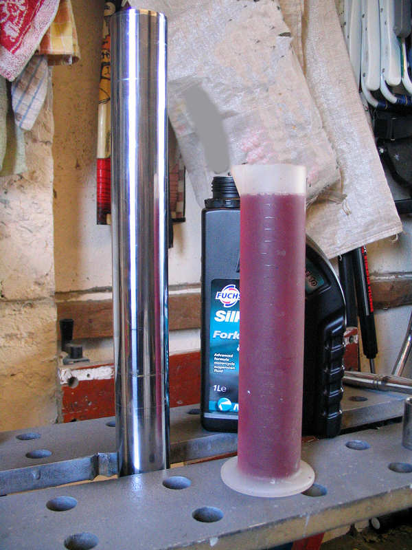
| The service manual states that 488mls of oil is required for each fork leg. This can be a pain to measure. I bought one of these measuring containers a few years back. It holds 250ml and is marked in 10ml graduations. I usual just measure 490mls and have done with it. If you want to be really precise, then I suggest you get a 10ml syringe and you can then draw off the odd 2ml. |
 |
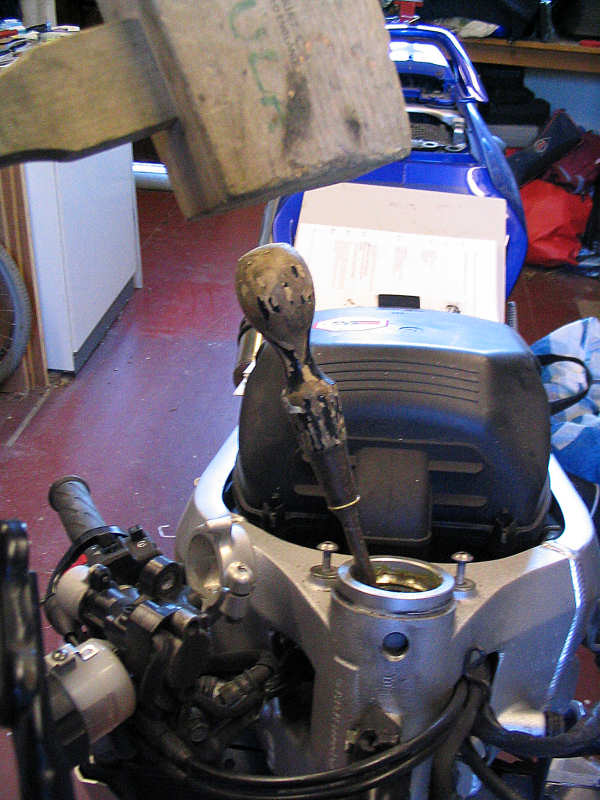
| Once the oil is poured into the empty fork leg, the spring, spacers and washer have to put back in. The most awkward part is putting the cap back on. As you can see in this photo the thread is really fine and it can be quite easy to cross thread when replacing. It's not helped that you have to apply downward pressure onto the spring before the cap can be turned to engage with the thread, so care is needed to get the cap on square and turn slowly to ensure the thread is engaged properly, all this while the spring is trying it's best to propel the cap across the garage. |
 |
| Masking in place and some PJ1 engine gloss is applied. Not a perfect solution but I reckon engine paint will last longer on this part than any other. |
 |
| Same thing for the radiator. Not quite finished here, anther coat was needed. |
 |
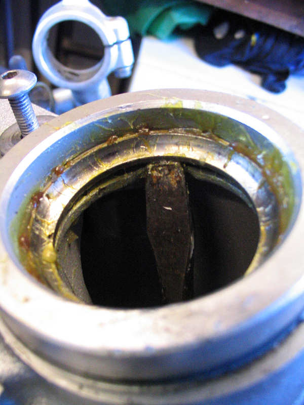
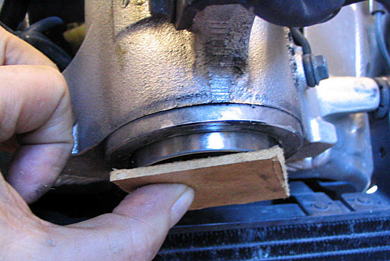
| At this point I decided to start re-assembling the steering. After placing the headstock and bearings back in the frame I tested the feel again. I wasn't entirely happy that the bearing were as smooth as they could be, some very, very slight clicks were felt, that only a very fussy person might notice and you probably wouldn't feel once all the weight of the forks and wheel were back on. So I decided that I might as well replace them rather than have strip everything down come MOT time in June. So this photo just shows the process of knocking out the bottom bearing from the top. |
 |
| The bearing rests against a rebate and there are a couple of notches in the rebate that allow you to get behind the bearing with a drift, or in my case and old screwdriver. The bearing is obviously missing in this shot. The bearing will only come out square, so you tap on alternate sides to gradually ease the thing out. |
 |
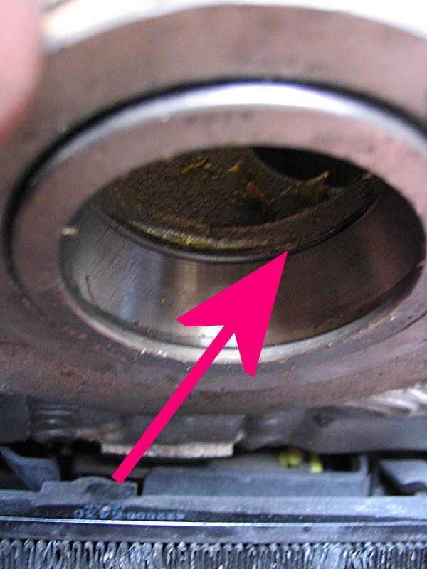
| Same again for the top bearing, but this time from below. |
 |
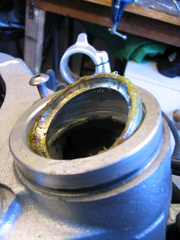
| And out pops the bearing surface. |
 |
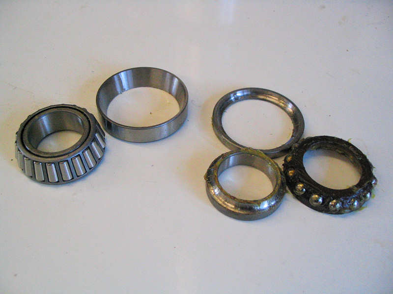
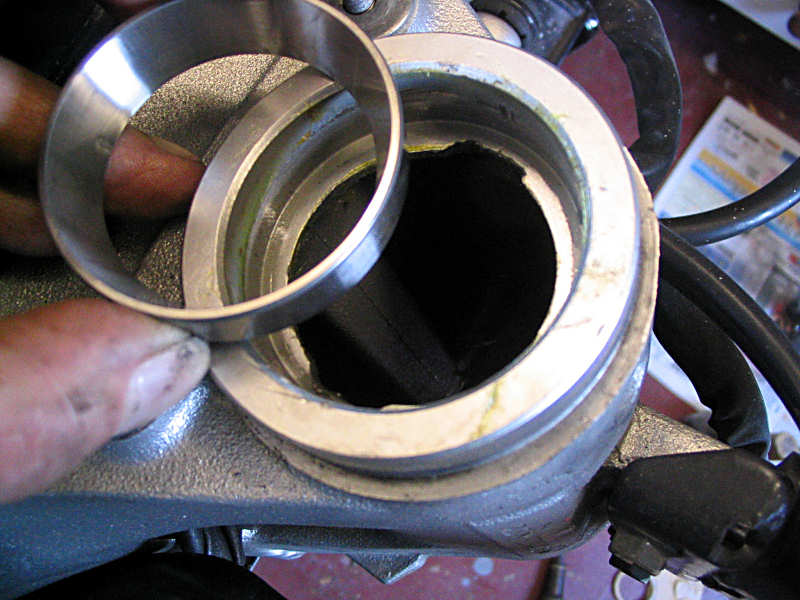
| I chose to use tapered roller bearings as replacements. They're more robust and spread the load better on their contact surfaces. They cost £30 from Busters and are made by Koyo, same as the originals. This shot shows them assembled with the original bearings in the foreground . |
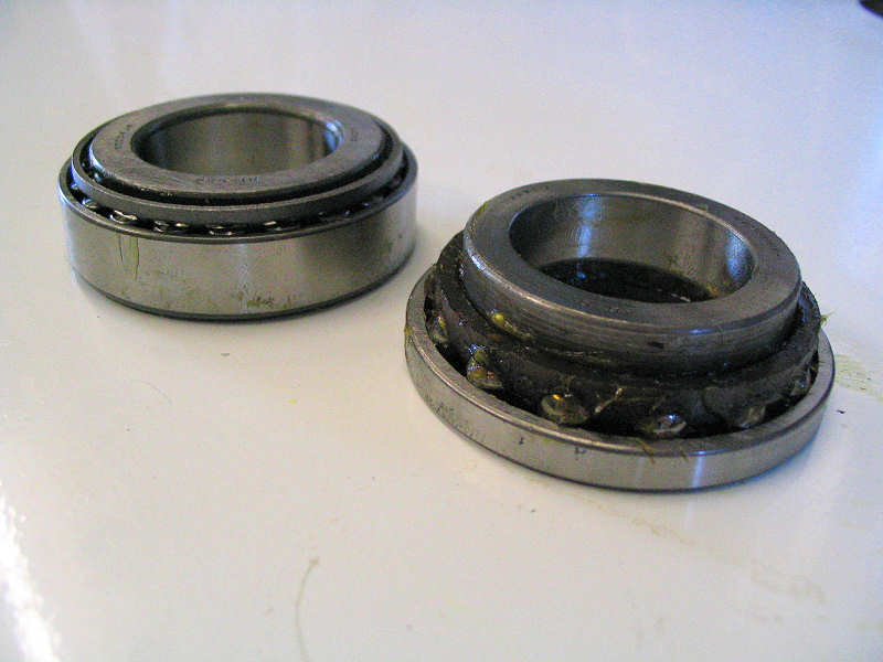 |
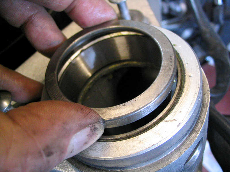
| Another comparison shot but this time disassembled. The rollers are held in a cage and not loose so therefore quite easy to work with. |
 |
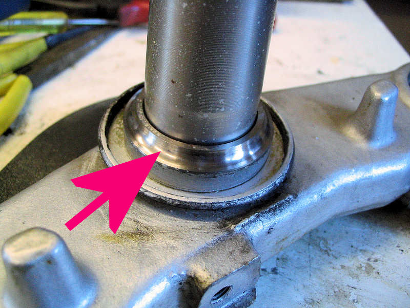
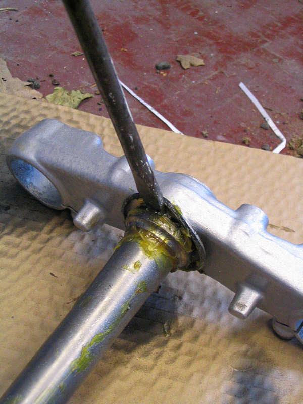
| This is the bit I dislike most about this job. The bottom bearing surface is a tight fit on the stem and needs to be prised off using a drift with a pointed edge, in other words a screwdriver. You have to pull this off square too, so you work your way around the stem tapping away and gradually moving the bearing up. The stem looks the same diameter along it's length, but it isn't, so once you get the bearing a couple cm away from the bottom yolk it becomes loose and can be pulled off easily. The poor thing being bent here is a dust seal. It's just a thin piece of tin with a rubber ring round the edge. |
 |
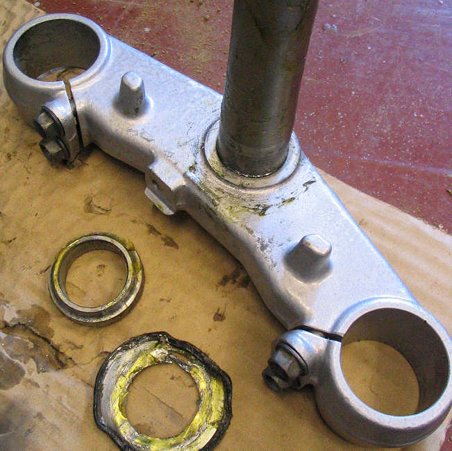
| Finally the bearing is off. The dust seal suffered in the struggle. |
 |
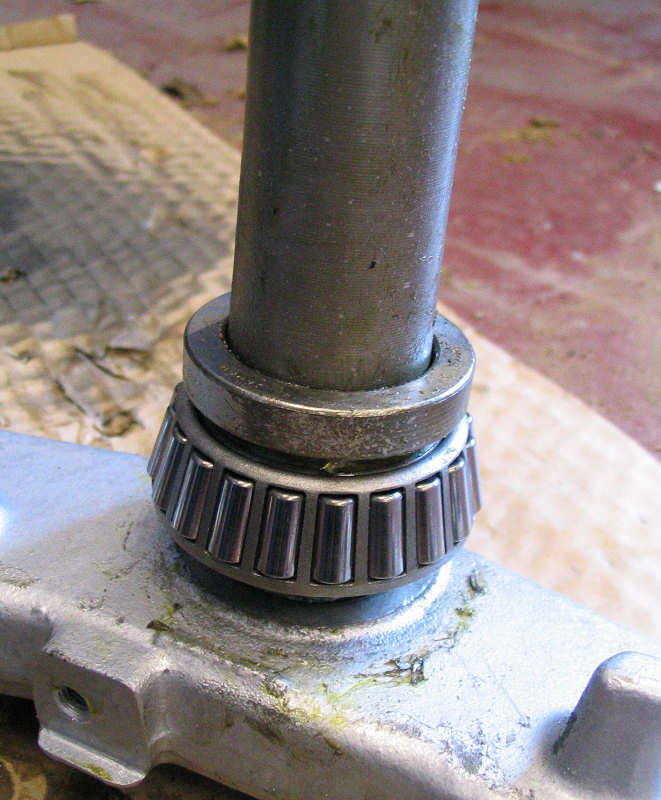
| Now the new bearing is tapped into place. I'm using the old bearing as a drift to give protection. Again you tap away moving around the circumference until the new bearing is flush with the bottom yoke. Don't use the old bearing all the way down as it will start to grip the step and you'll have to prise that off again. You'll notice that there is no dust seal now. I could have ordered one but I've already been waiting two weeks for the top dust seal to arrive. I'll live with the risk, it's not as though they were needed in the past on other bikes I've owned. |
 |
| Time for the headstock. This part of the new bearing has a very thin edge, so whacking it with a hammer is not a good idea. In this photo I'm using a spare piece of wood so that the hammer doesn't come into direct contact. Again you have to insert this part square with the headstock, so tapping gentle on either side is the way to do it, or working your way around in an circle. |
 |
| It's important to ensure that the bearing is in contact with the rebate all the way around. You don't want the bearing to move while your riding. |
 |
| Now for the top. Same thing again, drop the bearing in square and tap in using a piece of wood. |
 |
| Once the bearing is flush, use the old bearing as a drift to get the bearing seated against the rebate. And that's as far as I can go this week as I'm still waiting for the top dust seal. Argh! |
 |
|
The following week |
|
| Hurrah, the dust seal is in the shop. £10 for a bit of tin covered in rubber. In this photo the seal is in place along with the first ring nut. At this stage I gauging how much to tighten the ring nut, too loose and the forks will move and clunk, too tight and I'll damage the bearings. |
 |
| The second locking ring nut and washer is then attached and tightened. The top yoke is then replaced, the ignition barrel attached and the forks slid into place. Once everything is in the right place and both forks are flush with the top yoke, all the bolts are tightened. |
 |
| An oil change was due, so I tried to start the engine to warm things up which makes the oil thinner and therefore pours out quicker. It took a good 30 secs of pushing the starter button and getting nowhere before I realised that I needed to connect the fuel tank and therefore the FI pump. Doh! So once that was done the bike started just fine. It's worth buying one of these containers for the old oil. The oil goes straight into the can and I just take this direct to the recycling centre. |
 |
| I bought a K&N air filter some time back (see above somewhere). It did look grubby and the beauty of this item is that it's washable. So got a suitable deep tray and filled it with petrol and rinsed the filter out. Easy. |
 |
| As I had the front wheel off, I thought I'd give it a good clean. So to make life simpler still I removed the discs too. As you can see in this photo there is some discolouration. I can recommend Halfords Alloy Wheel cleaner for this and all sorts of other cleaning tasks. My usual approach is to remove oil and grease with some white spirit and a paint brush. This loosens most of the much. The wheel cleaner then finishes the job and you get a superb clean shiny surface. This photo is the before shot, I did manage to get it cleaner but there is still some discolouration. |
 |
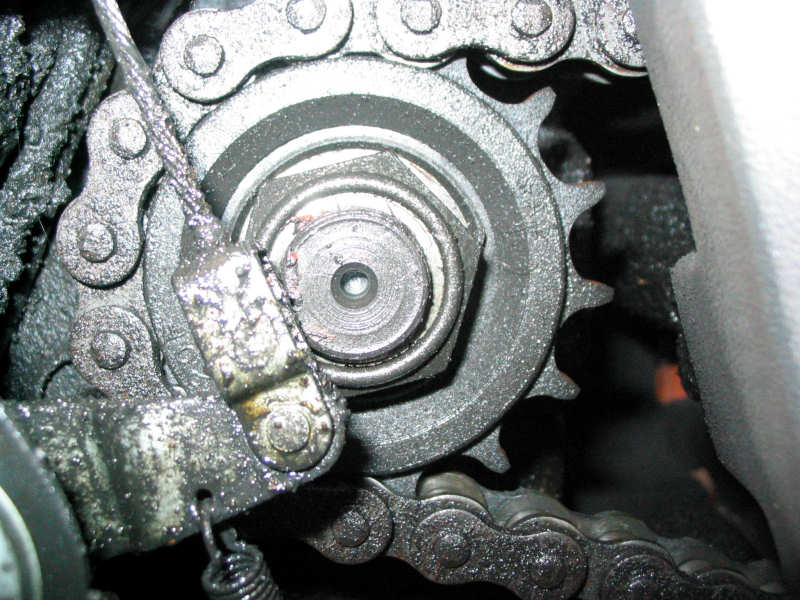
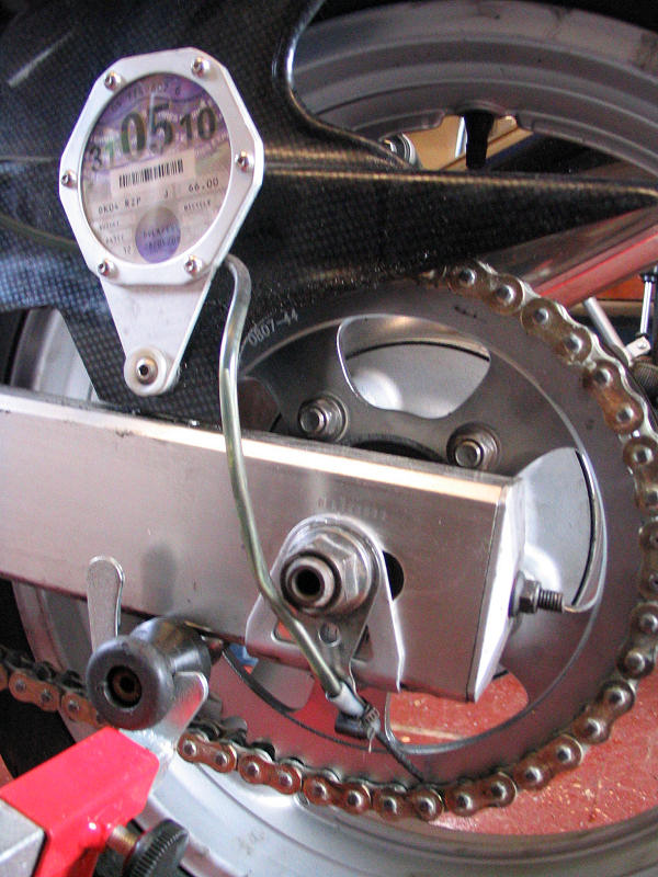
| I know from experience that checking chain and sprocket wear shouldn't be taken lightly. Thanks the to Scottoiler the chain has hardly stretched in 19k miles. The rear sprocket looks okay but that doesn't mean the front sprocket is okay too. So time to get the cover off and take a look. The photo shows some wear but there's no sign of 'hooking' yet. Whilst the cover was off I gave it a good clean using the approach mentioned on the wheel |
 |
| All back together and time for a clean. A quick test ride confirmed that there was some 'clunks' coming from the front end when braking. Looks like the head bearings are too loose. I should point out that I could feel no clunk when using the usual test of grabbing the bottom of the fork legs and pulling back and forth (with the wheel in the air). So I spent another hour or so gradually tightening them until the clunk was no more. Another test for this is to push the bike along and apply the front brake and listen for clunks. This approach is okay but in my case some of the clunking was from the disc pads moving in the caliper. |
 |
|
The bike has now been in regular use for the
last week and there has been no problems. I can't say the steering
feels any different to before except that it feels a little lighter.
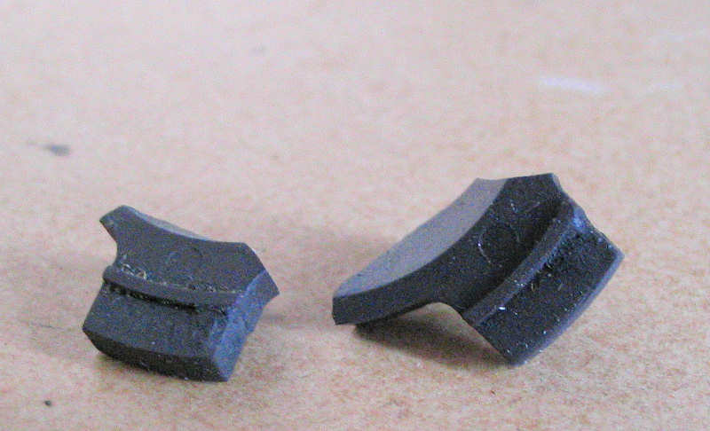
Such a great buzz to be back on the bike. The photo on the right shows a couple of pieces of plastic that I found on the garage floor halfway through this rebuild. I could see that they were part of the SV but had no idea where from. The answer came when I put the front wheel back on. These are lugs off the speedo drive. I must have misaligned them last year and broke them. They fell out this year when the wheel was taken off again. The speedo works fine with two lugs but I'll be keeping an eye on Ebay for a replacement. |
 |
|
Winter 2009-2010
|
|
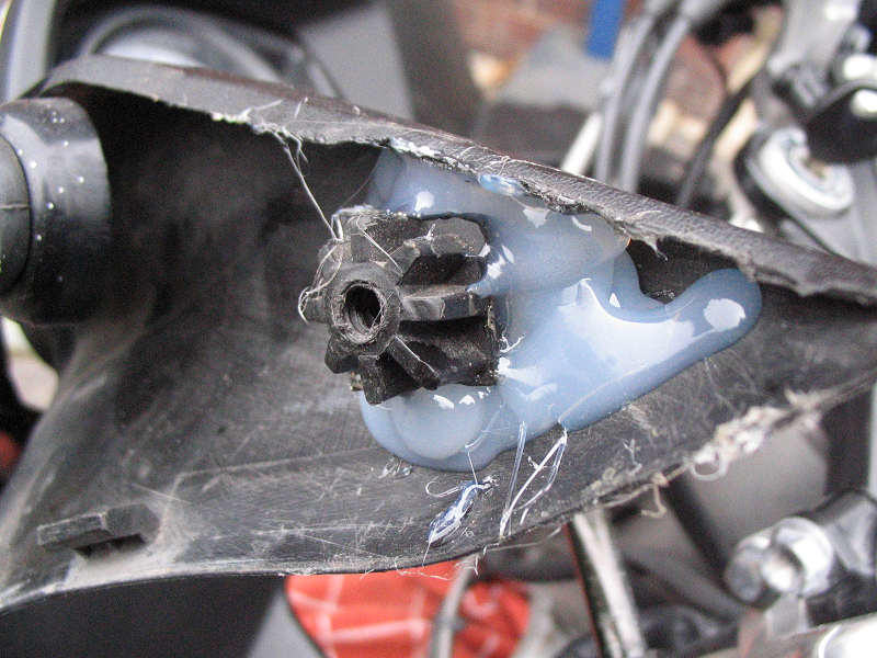
| This is the inside of the fairing filler piece. This pointed section is at the edge of the screen just behind the wing mirror. Remember my drop at the end of last summer where the bike fell off it's stand onto some railings. The right wing mirror was snapped off and the fairing behind was also snapped. This filler or inner fairing was more flexible but this lug was broken off. The lug doesn't do much other that hold the top of the filler in place. A screw goes through the fairing from the outside and into this. |
.JPG) |
| These panels were going for £15 on ebay, and I wasn't going to pay out good money when cosmetically the filler was fine. It's not a load bearing part, so I thought a strong glue should hold it. The walls of the lug are quite thin, so there's not a lot of contact patch for the glue to act on. I've dealt with problems like this before, and the answer is to use splints to increase the glued area. Fibre glass webbing or similar with resin can do a great job but this is too small and fiddly for that. So first job was to glue the lug in place with Araldite. |
 |
| I let the glue harden for a bit, then added these strips of fibre reinforced tape. On one edge I used some clear plastic from some bubble packaging, that had some 90degree folds already moulded in. Seems to have done the job but time will tell. Doesn't look too pretty, but then no ones ever going to see it. |
.JPG) |
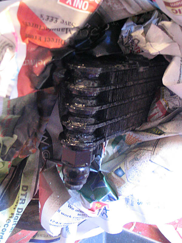
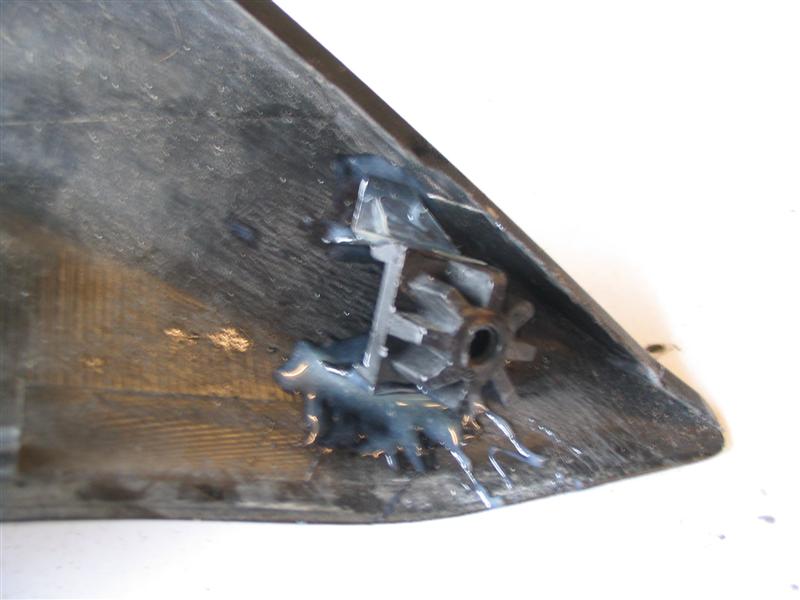
| I thought last year that the chain was making more noise than it should. The bike has now covered 24k miles and that's pretty good going for one chain. The Scottoiler does keep the wear down. I know from experience that the gearbox sprocket was likely to be more worn that the rear, so I popped the cover off for a quick look. with so much black grease and oil about, it was hard to judge, so I put a piece of white card behind to get a better view. I'll let the photo speak for itself, but those teeth look worn and hooked to me. Time to order a new chain and sprocket kit. |
.JPG) |
| This is the rear sprocket. Some wear but not as bad as the gearbox. The chain itself still looks fine. It's barely stretched and only gets adjusted when the rear tyre gets replaced. |
.JPG) |
|
The following week |
|
| Removing the gearbox sprocket, involves flattening a retaining washer and a lot of effort. A motor cycle shop will use an air impact hammer to do the job, pure muscle doesn't work. I bought this electric impact hammer from Aldi a couple of years ago, it's really intended for undoing car wheel nuts, but it has an 1/2 inch socket drive and it works just great with a 32mm socket. All for £15. Having said that it can still take some time to break the nut loose. I locked the rear wheel using the brake and sat there for a good 5 minutes before I saw some movement. So a good investment. |
.JPG) |
| A nice new gold plated EK chain arrived during the week. Along with sprockets. Here you can get a better look at the wear on the right hand sprockets. A nice spiral pattern! |
.JPG) |
| A closer look |
.JPG) |
| I'm not going into a lot of detail about chain replacement, as I'll be duplication the item I wrote on my mk1 SV, click here to see. Needless to say. I've loosed the rear axle, pulled of the chain to allow some slack to gear the front spocket off. Installed the front sprocket and loosely tightened the nut. The chain was then hooked back onto the rear sprocket. | |
| Used my angle grinder to take off the rivet heads on one link. You can the prize the outer link off with screwdriver. |
.JPG) |
| Attach the new chain to the old. Draw the new chain through the sprockets by pulling the old one. Detach old chain. At this point locate the join link and place the O rings and grease and per manufactures instructions. The add the outer link as per photo. The outer link is a tight fit over the pins and I had to use mole grips to press it on, moving from one pin to the other alternately and gradually easing it one. How do you know when you've pushed it on enough. Too far and the link will be tight plus you'll crush the O ring. This chain came with some spacers, shown in the photo, these stop you pushing the end plate on too far. |
.JPG) |
| The plate is now on as far as the spacers will allow. Note the hollow in the end of the pins. A riveting tool would now be used to squash the end of the pins into a mushroom to stop the link coming apart. I don't have a rivet tool. I used a couple of hammers. I place a big club hammer in the inside of the link and uses a smaller ball headed hammer to flatten the end of the pins, again with the spacers still in place. I've always done it this way and never had a problem. I suppose I should use a riveting tool but that's more cost and something I'll only use every few years. |
.JPG) |
|
The following week (nothing happened so this is two weeks later) |
|
|
The side plates on the rear axle were looking
shabby again. I'd love to get these made up in stainless steel, but it would
probably cost far too much. I could make them myself but drilling out the
centre hole would be a problem. Other option could include electro-plating of some sort, but I'd have to get them very clean before the plating would take and these are a bit too pitted. So the short term fix was to wire brush them and paint with Hammerite. They now look a lot better but probably won't last.
|
 |
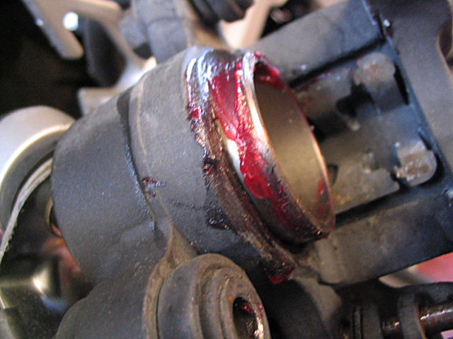
| Whilst playing with the rear end, it made sense to check over the rear brake, just as well I did. Plenty of meat on the pads but the pin and it's cover plug were corroded. I didn't have too much trouble getting the pin out but as you can see it was rusting nicely. This is despite using Copperslip to protect it. So a good clean and lashings of Copperslip, and put back to gether. |
 |
| I then pushed out the piston using the brake pedal a little way. Cleaned off the muck and gunk and re-greased with rubber grease. Piston then pushed back to allow the caliper and pads to engage with the disc. |
 |
| I knew I had some paint to touch up. The experiment last year with etching primer has not been any better at keeping the paint on the fork legs. I couldn't face stripping them down to bear metal again, so I just cleaned them and keyed up the surface and applied some aerosol paint. Much the same too for the radiator and oil cooler. |
 |
| Amazing how a little bit of paint can make something look so much better. |
 |
|
|
|
|
I didn't do a lot of work on the SV during the
winter months this year, I was far too busy decorating the house. Nothing
urgent needed doing anyhow just the usual servicing. One thing that has bee
bugging me though for a while is the front brakes. In a word spongy. It
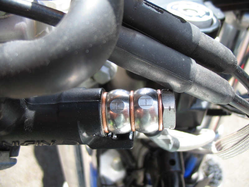
feels like there is air in the system, but I've already checked that. Given that the bike is 7 years old now I thought is was time to replace the front brake lines. For those new to biking, you may not be aware that the standard rubber lines fitted at the factory do degrade. They become softer with age and flex better, so any braking force applied to the callipers often gets wasted trying to inflate the lines. |
 |
| So a set of stainless steel HEL lines were ordered along with stainless fittings. To make life easier I removed the fairing, this gives better access and avoids the risk of spilling corrosive fluid on the paintwork. I tend to cover bike in old tea towels too, just to protect against accidental chips and scrapes. The old lines were undone at the bottom and I pumped out the fluid with the lever. I removed the filler reservoir too. |
 |
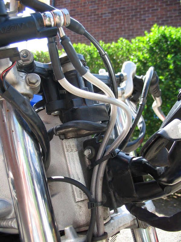
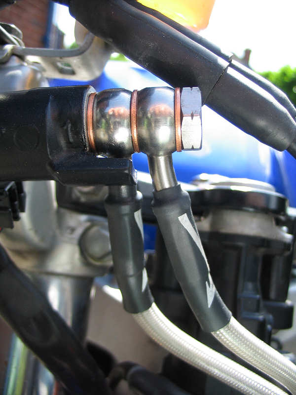
| I noticed that the banjos fittings on one end of the new lines were cranked and these go on the caliper end. I later noticed that one lines had cranked end at the other end. In fact I got a bit muddled until I twigged this. I should point out at this stage that I went for a twin line system, not the OEM three line. Two lines therefore connect on the master cyclinder end and a longer bolt is supplied to deal with this. The lines banjo connections are marked with a H at this end (see photos) and one banjo is straight (put this on first) and the second has a slight crank to avoid contact with the first line (again the photo should help explain what I mean. The bottom of the lines were then connected to the callipers. |
 |
| The next bit is very boring. Bleeding. New fluid was put into the reservoir and pumped through, by opening the bleed nipple on each calliper one at a time till all air is removed. Easy to say, but patience is required. I always seem to get air locks and I find tapping the callipers and alternating from one bleed nipple to other helps. It just takes time |
 |
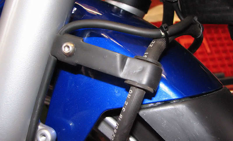
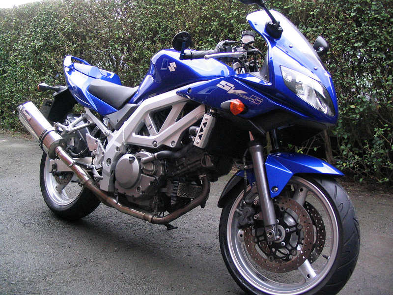
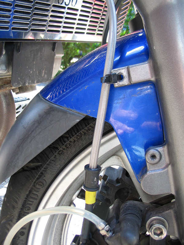
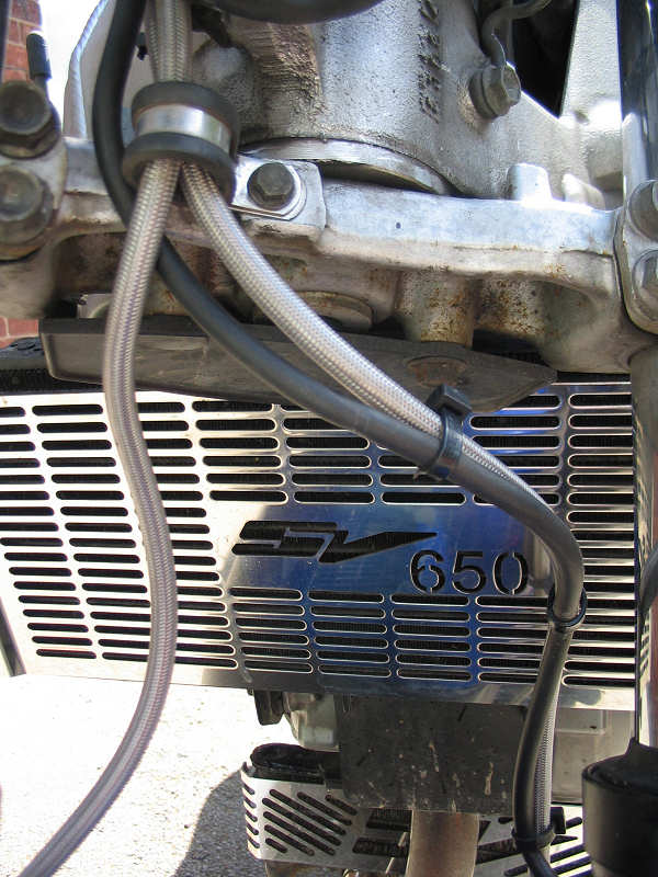
| Once you're happy that all air is out of the system, the next job is to clip the lines out of harms way. Given the odd nature of the pointy original lines, I have a clip already on the left fork leg and nothing on the right. I had one spare P clip in my garage and that got used to hold the lines to the bottom yoke. More P clips are on order. The cable for the speedo sensor also have to be tidied up and I cable zipped it to the left hand line. The photos tell the story. So did it make a difference to the braking experience, oh yes indeed. No more spongy feel, I can apply a lot more force to the brake pads with less effort on the lever, and the wooden feeling has gone. Feels like a new bike from that point of view. |
 |
|
Next Job |
|
| I've another trip to France planned for later this year and really irks me that I have a TomTom sat nav that I should be able to use but can't. I'd look at various SatNav cases for bikes and they vary in price and quality quite a bit. The Hein Gerieke looked the best option but that seems to have been dropped. Other option either required mounting to conventional handlebars or via a ball joint on the centre nut of the top yoke. I didn't fancy these options as have clipons and the centre nut location would foul on my tank bag. I really wanted to mount the SatNav in the fairing over the top of the rev counter. Now I could use the supplied suction cap and attach it to the glass of the rev counter but it's not reliable enough and if the SatNav fell off it could cause and expensive accident. |
 |
| So my solution was to buy a Navitech GPS case from Amazon for around £13 and also a waterproof cig lighter socket from the same. In the first two photos you can see how I mounted the socket in the fairing, hopefully out of the way of the worse of the weather. The socket is connected to the dip beam light circuit. As the lights are always on the socket is always live. The power adapter for the TomTom has a fuse built into it. |
 |
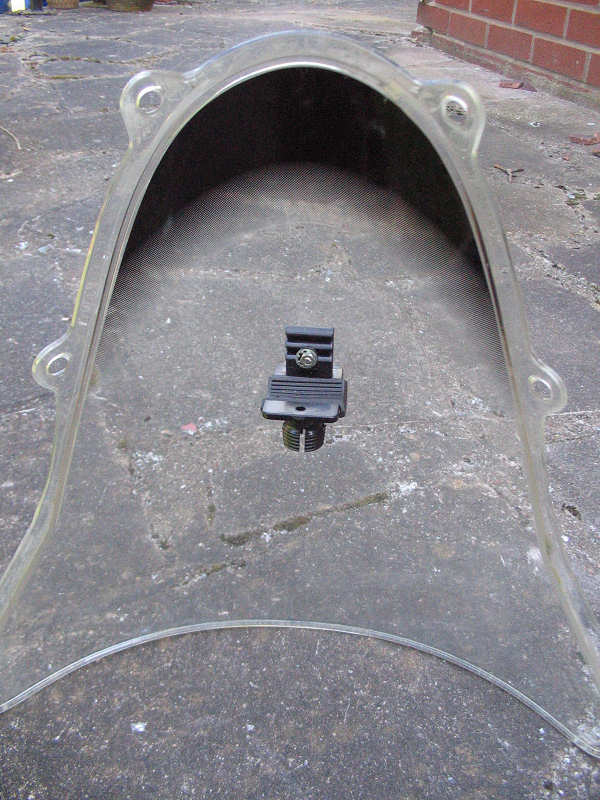
| I have a spare screen, so was quite happy to hack this about to test my idea of mounting the bracket. The bracket is half the supplied handlebar clamp supplied with the Navitech case. I've lined it up so that part of it rests against the top edge of the dash above the rev counter. |
 |
| Half the clamp |
 |
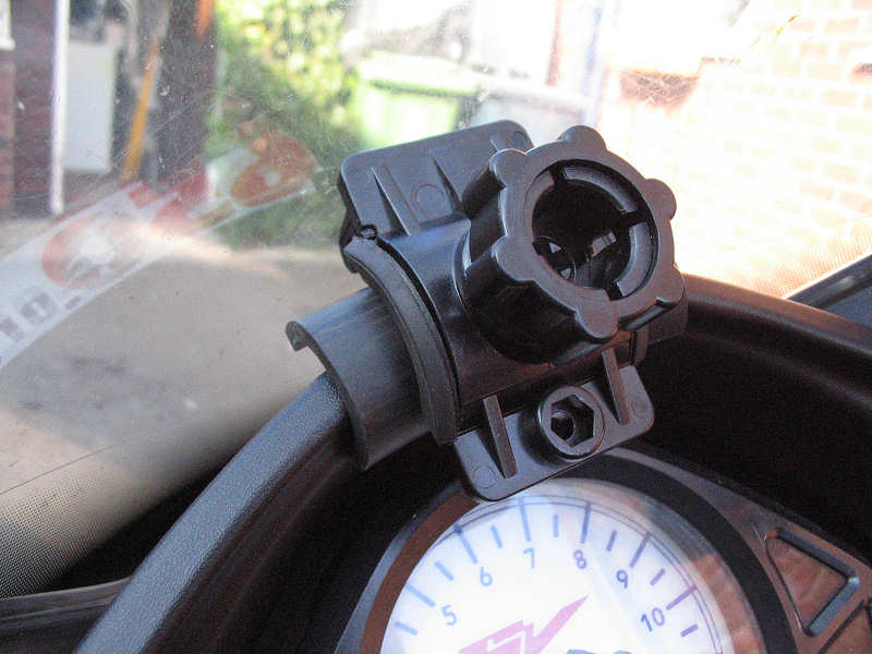
| Once the screen is in place, I put another piece of rubber behind the clamp to further support the bracket. A ball joint on the back of the Navitech case locates in the bracket |
 |
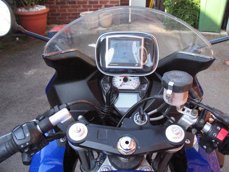
| Riders eye view of the SatNav. The power cable runs out of the bottom of the case through the zip (there is no dedicated hole for the power lead) to the power socket. Just make sure that the cable is shortened with a zip tie or similar so stop it get tangled is something is shouldn't. |
 |
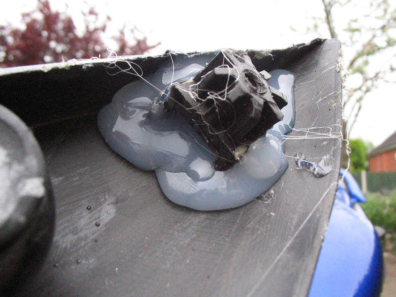
| Whilst improving the sat nav mount I managed to bust my previous repair on the lug inside the fairing inner. The previous repair is shown above. Good old Araldite didn't bond with the plastic as well as I hoped. So time for a change of approach. One of my favourite tools is the hot glue gun, it's useful for all sorts of things. So i've gone for the plaster it on good and thick approach, maximising surface contact area. So far so good. |
 |
|
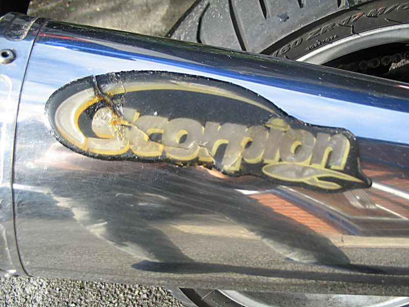
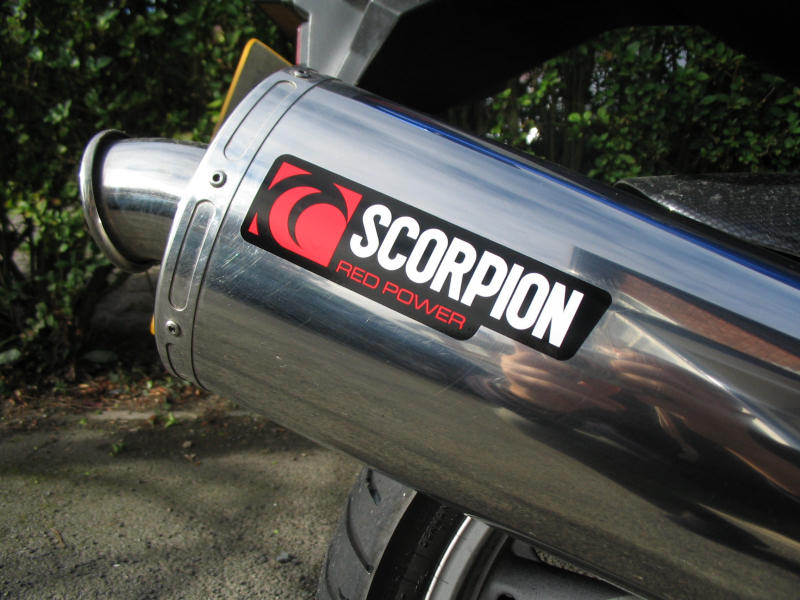
It came to my notice that the Scorpion sticker on my end can was looking a bit sad. The heat had cooked the rubberised material that it's made from and cracks were appearing. The colour had also faded and the glue was about to give up. Not a problem thought I, I'll just pull it off and remove said glue. But it occurred to me that the can would look a bit plain without the Scorpion motif, so I dropped an email to their service department and asked if I could obtain a replacement, hoping they would send one for free. And guess what they did. It looks nice too, though it does look like a bumper sticker and I suspect it will end up looking like a small toasted slug after my first ride. I'll let you know. |
  |
|
|
|
| I started late again this year. Nothing major planned for this season except to replace the wiring loom. Why, well I've always hated though I recognise it's deterrent factor. So earlier in the year I bought a 2004 wiring loom of eBay and was waiting for the winter strip down. Replacing a wiring loom is fairly straightforward, just a pain. On some bikes the loom is easily accessible, as it's just cable tied to the tubes of the frame. This is true on some points of the SV but some in the engine area, where access is dire. |
 |
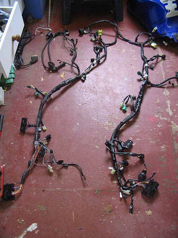
| I removed all the bodywork and tank and laid the new loom along the length of this bike. The new loom is suspiciously clean and I also wanted to check the headlight end in case I'd been sent a naked version. All looked good till I got the the area near the seat lock. I had an extra component. It's a headlight ballast resistor that has been fitted since 2005. So not a 2004 loom after all. |
 |
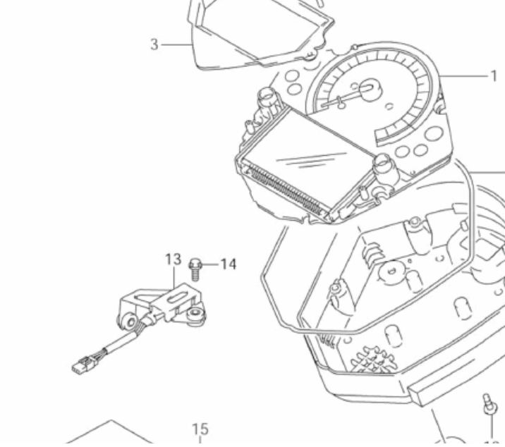
| To be honest I wasn't sure what it was to start with. It's clearly a resistor designed to take a heavy load, but the forum helped as did a bit of googling. Looking through parts fiches at Alphasports didn't help till as I couldn't see it listed on the pages that the show the subframe area. For reason, Suzuki show it on the pages that cover the speedo parts, you can see he it here. |
 |
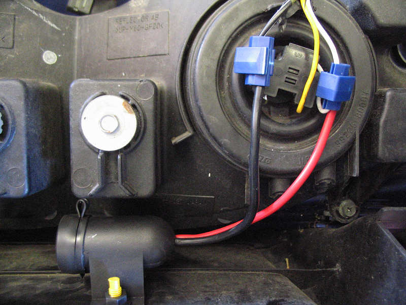
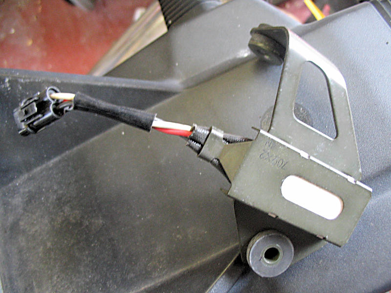
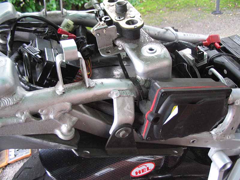
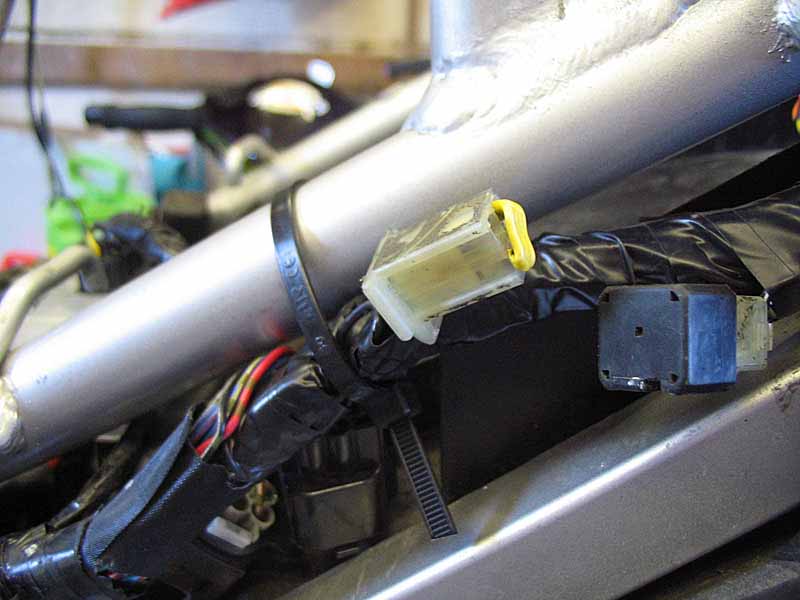
| The other piece of the puzzle is where does it mount. Clearly the fiche doesn't help. The plug on the loom is short as is the lead on the ballast so it has to go near the seat lock under the bodywork. I eventually found this image which gives a clue. |
 |
| So the question was, do I proceed? Removing the wiring loom in the engine bay was going to take a lot of skin off my knuckles (have you seen where the rear coil is). All the plugs and other connections looked fine. What If I spent hours replacing the loom and find either nothing works, or I have shorts or worse still blow the ECU. I decided it wasn't worth the risk. I'll keep the new loom, as a spare should the alarm give up the ghost. | |
| So next jobs. The bike still had another 500 miles to the 32k service, so i concentrated on cosmetics. The top yoke and forks were all chipped and scratched. The top yoke does not want to retain any black paint I spray on it, so time for the paint stripper and a fresh coat of Hammerite smooth silver. I've always found that silver is fairly robust, the black goes to thin on edges. |
 |
| Forks were washed, rubbed down and primed. They were then painted with the same Vauxhall metalic grey and given three coats of lacquer. |
 |
| One causalty. The stone guard broke on disassembly. £14 to you. |
 |
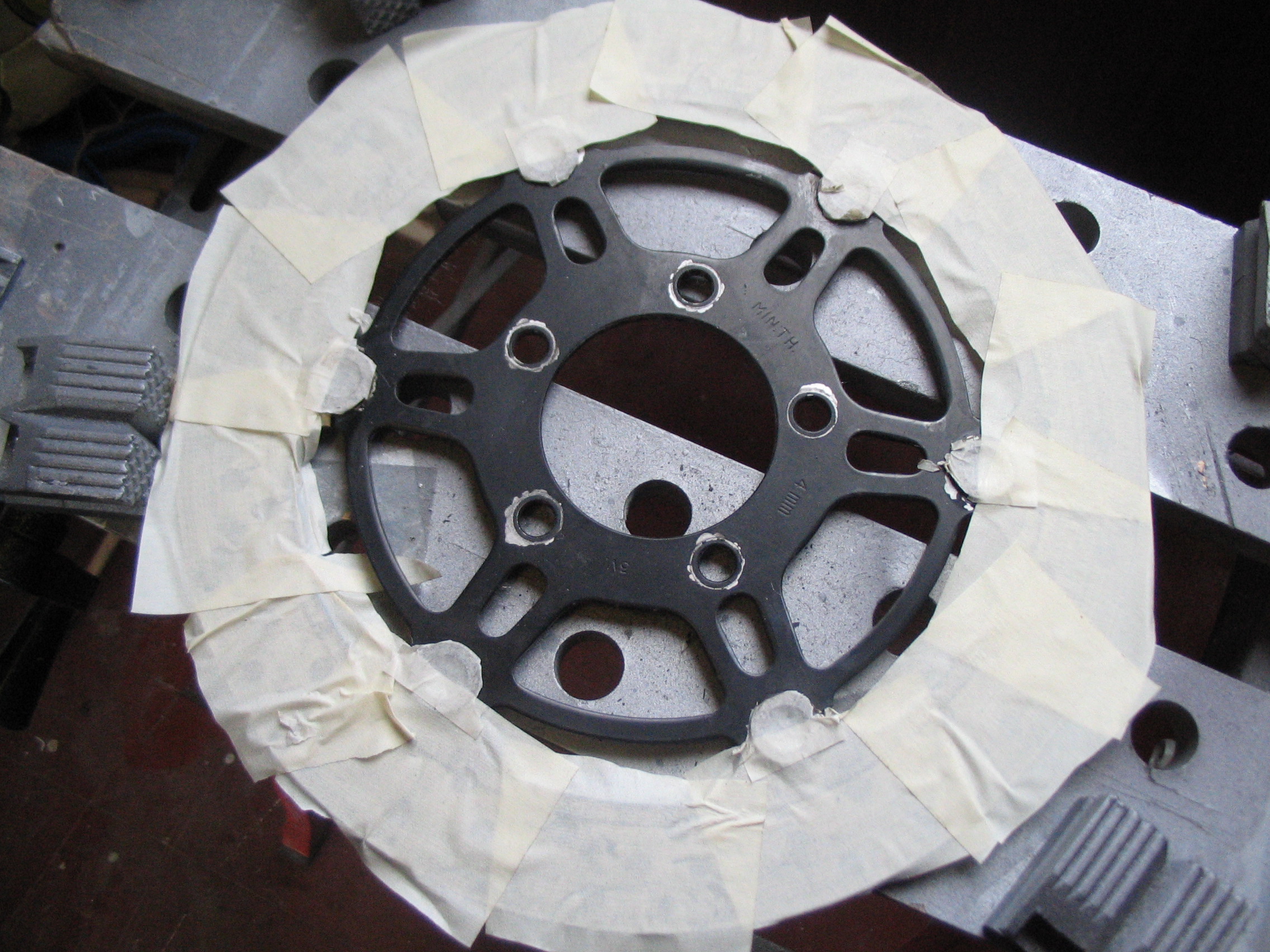
| Discs were looking shabby too. So again looks of cleaning |
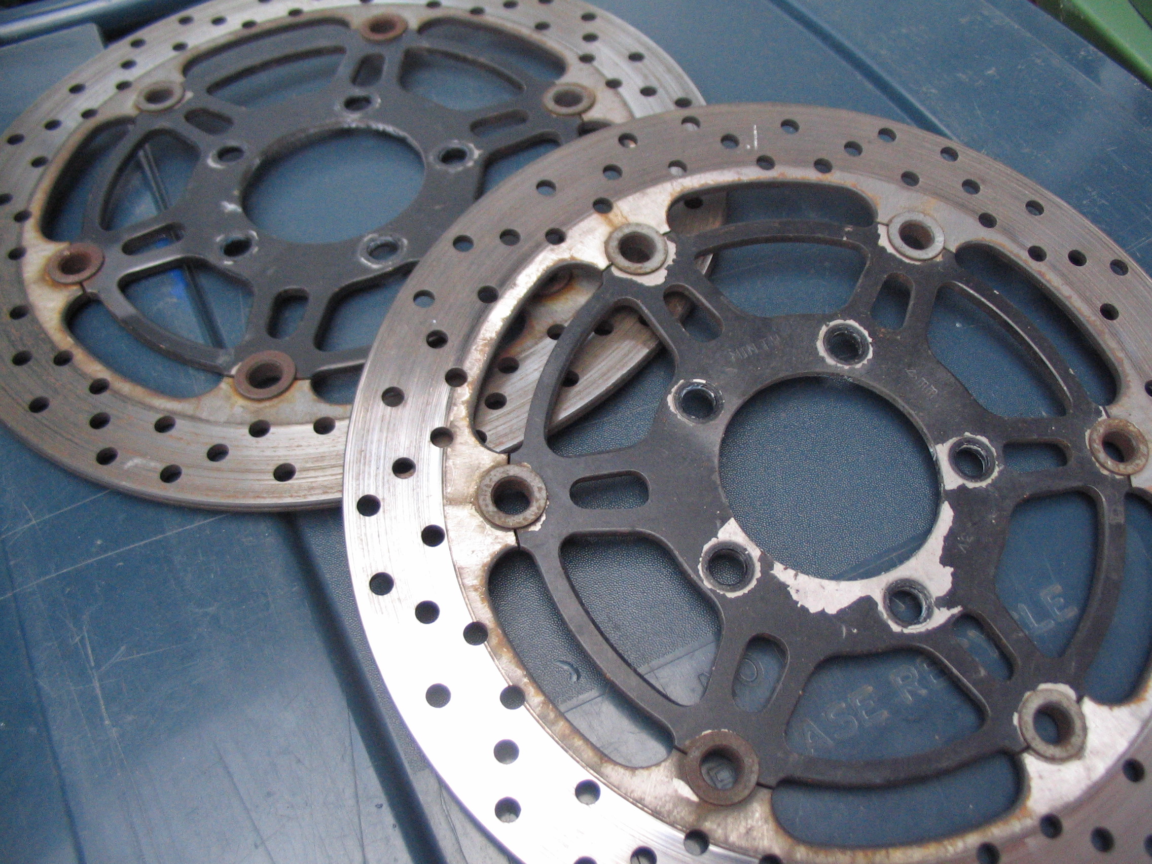 |
| Masking was a pain. I used Hammerite satin black on these. |
 |
| Another item look shabby was the fan housing. Rust was starting to break out on the metal work. |
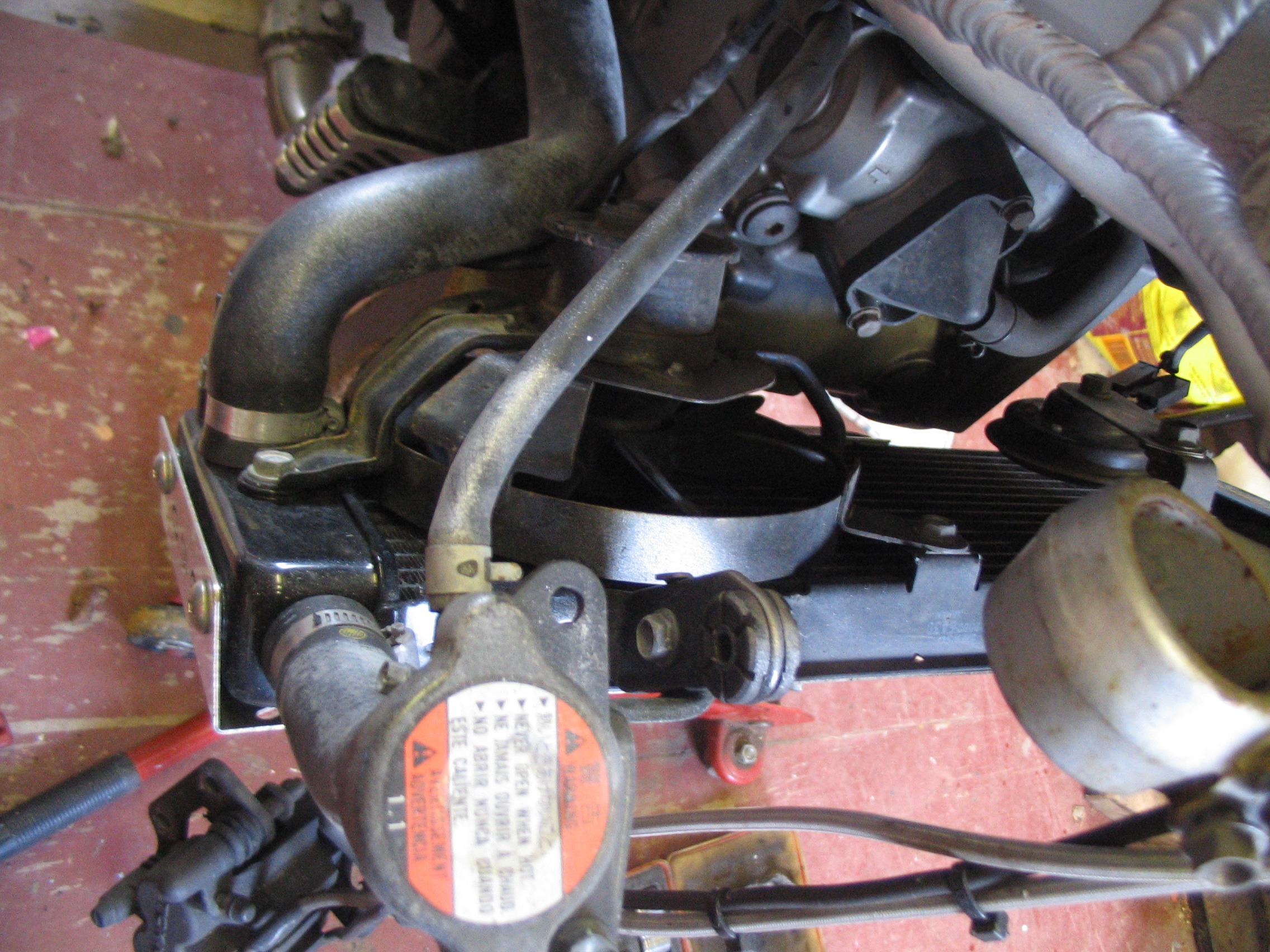 |
| I saw a fan from a 2007 SV on eBay for £15 and bough that. There was a slight problem with fitting it though. I thought the rad and it's associated parts were all the same from 2003 onwards. Clearly not |
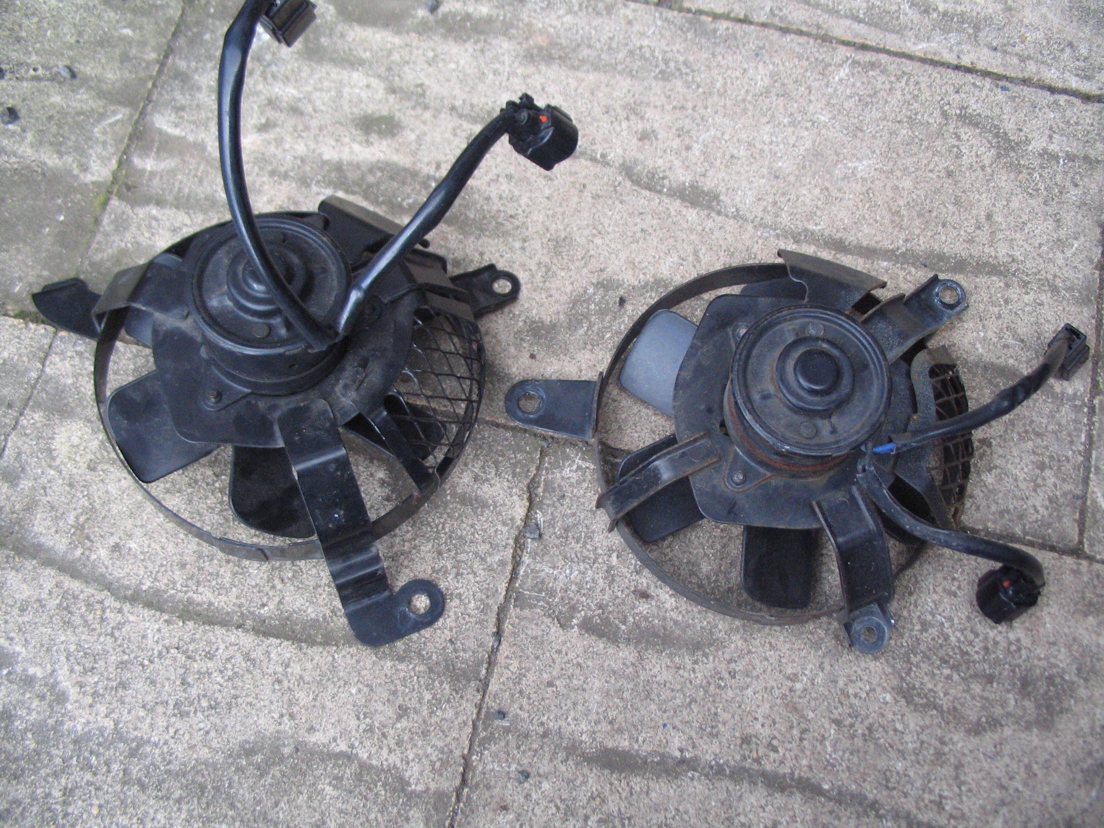 |
| So back to plan B, use Hammerite satin black again. |
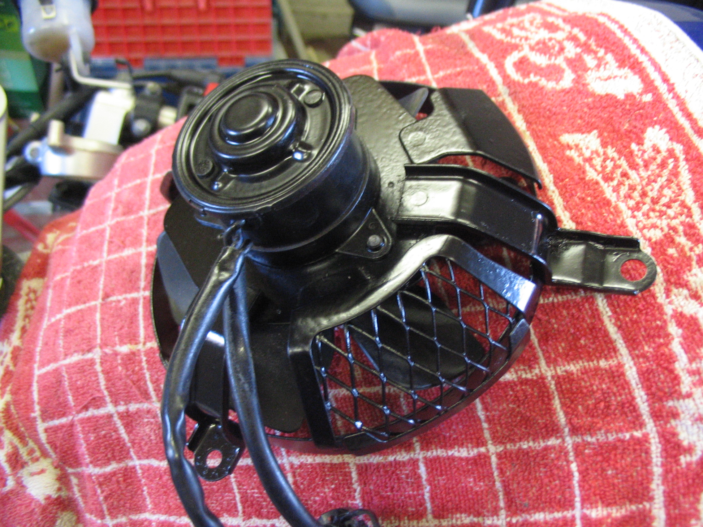 |
| All back together again and looking tidy. I had to move the bike out the garage at this point as my freezer had gone bang and a new one was being delivered. Access through the garage was required. The 32k service is nearly due as I write this and I'll do that in the drive. Lots more cleaning to do, but the most important thing is that my winter is over and I'm riding again. Anyone wanna buy a 2007 fan? |
 |
|
Spring 2012. Service time |
|
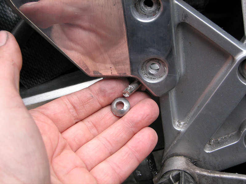
| It's now just turned April and the SV has hit the magic 32k miles. So time for some more servicing. Nothing too exciting here, oil was drained and refilled with fresh Castrol GP1. Spark plugs were replaced too. Due to my laziness these hadn't been replaced since the 16k service. Whilst changing the front plug I looked at the the front exhaust retaining bolts. The thought occurred to me that these had never been removed and what were the chances of them being corroded solid, thanks to the battering they get from the front wheel. I used a good quality Allen (hex) socket and did the trick of tightening the bolt slightly first. This is a good technique as it gives you a chance to test resistance without burring off the bolt head. I got a nice 'click' as the bolt gave up its resistance and I then easily removed both bolts. Putting them back in was another story. The right side bolt was very tight and I was worried about cross threading and buggering up the internal thread. This is another good reason to have a tap and die set to hand. As well as cutting new threads they're also very useful for cleaning up corroded items such as this. Most sets come with pitch key that looks like a set of combs. You use this to work out the pitch of the thread. Mine was 1.5 (turns per mm). The bolt size was 8mm. This is not the spanner size, but the width of the bolt body itself. So I selected the right tap (taps cut threads in holes, dies cut threads on bolts) and gently would it in and pulled out all the crap. Fitting the bolts after that was easy, along with some copperslip to prevent further corrosion. |
 |
| Whilst working on the bike in the garage in February I noticed that the front tyre was pretty flat. Enough for me to start looking for screws and nails, but nothing obvious was found. I always buy my tyres from Autotyres in Frankwell, Shrewsbury. A nice bunch of lads and one of the few places that although geared up for cars will also look after bikes, provided you can give them a loose wheel. So I dropped of the front wheel with them and picked it up a couple of hours later. Puncture was fixed as expected, the cause, bird poo apparently. The put the wheel in the water tank and air was escaping between the rim and tyre. The tyre was removed and offending excrement was discovered. My bike is parked outside my house most of the year and mostly covered, but we have a large population of Blackbirds leaving in our hedges and trees so I wasn't entirely surprised. Best bit is that Autotyres charged me nothing, good service still exists. | |
| Whilst working on the front wheel it seemed a good idea to check the front brake calipers over. Nothing much to note, just a clean and re-assemble. I thought I ought to look at the rear too, as I can't recall the last time I checked. The pads still had plenty of meat on them but the shims and packing plates are well rusty. One of the rubber boots was torn and the plug that allow access to the single pin was frozen. I was able to remove the plug by tapping it around with a centre punch but that wrecked it. So onto the Robinsons website to order spares. It was cheaper to buy a pad service set than just the shims and packers, so I did that. Interestingly the new shims are plain metal, no paint and hopefully corrosion proof. I wasn't happy with the feel of the front brakes, a touch spongy I thought, even though I bled them to death last year when I installed the brake lines. So I bled them again on the off chance that some trapped air might have moved. I saw a couple of tiny bubbles on the right caliper, but not much else. This did transform the feel though. Sponginess has gone and response is immediate. |
 |
|
|
|
|
As mentioned above, my SV came with a Datatool 3 fitted. This didn't
particularly bother me, in fact I thought it a bonus. It soon became
apparent it wasn't. As I rode away from the sellers house, I headed for a
petrol station to top up. Having no clue, I switched off the ignition and
unlocked the fuel cap. Of course you can guess what happened after 30
seconds, the alarm engaged and then went off as I sat on the bike pumping
fuel. In my ignorance I though that I would have some control over when the
alarm was engaged and that the default self arm time might be something
sensible. I've lived with the damn thing ever since, but I've always worried about what would happen should the thing fail completely. I've mentioned before that I've already got a spare loom (bought with this in mind), although from a later model, but as the bike wasn't broke I decided to leave it. |
|
| So you can now probably guess that 6 months later my premonition came true and the alarm refused to disarm when I left work on a Friday evening. Luckily I had set an override PIN but I didn't know how to activate it! A quick Google gave me an owners manual and I got the bike started and got it home. | |
| Over that weekend, as I played with the alarm, it was clear that the fault was intermittent. I had two fobs both with good batteries and sometimes they would work and sometimes not. For the sake of my blood pressure I put the alarm into service mode and covered up the speaker with gaffer tape to suppress the constant beeping |
 |
| I rode around like this for a week but I was concerned that the alarm might go into a full failure at any moment and stop the bike dead in it's tracks. I did some more Googling about the removal of alarms and most seemed to think that removal was straightforward, including a thread on this sites forum. Logically it is. The alarms wires either tap into the existing wire, a simple join, or break into it by cutting an existing wire and intercepting that circuit. | |
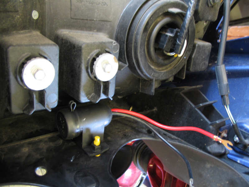
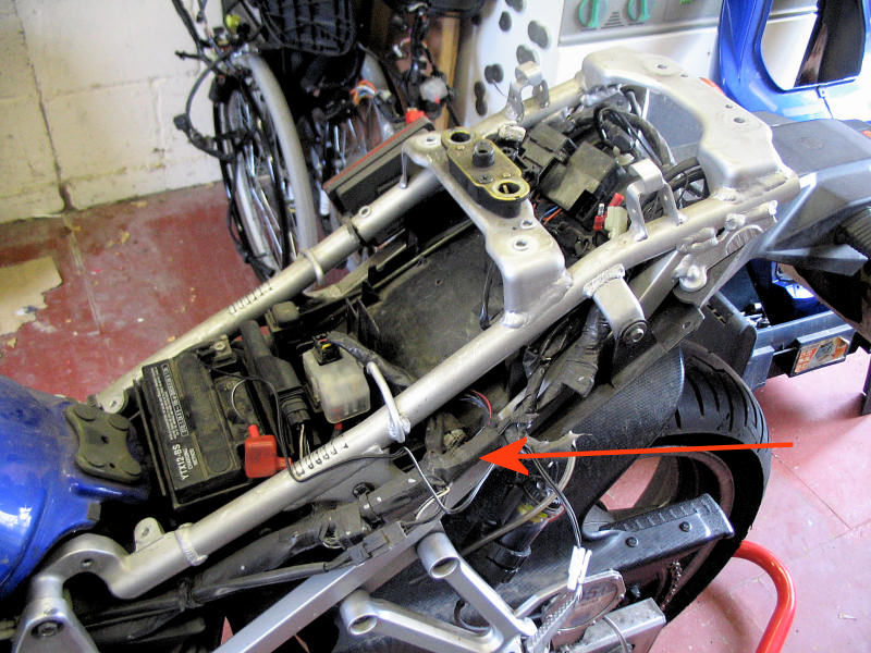
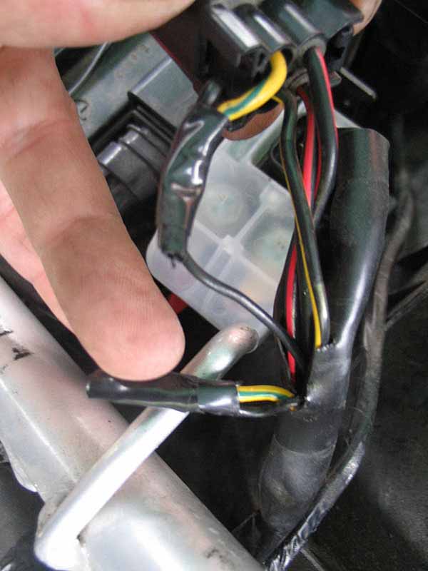
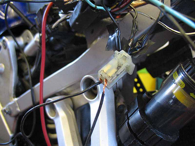
| So I made a start. I unwrapped the tape on the loom on the left side of the subframe and worked my way along each alarm wire. First wire was on the starter solenoid, seen here in this photo, this is an intercept. I removed both alarms wires and rejoined the green/yellow to restore the original circuit. The joints were soldered and shrink wrap applied for reliability. |
 |
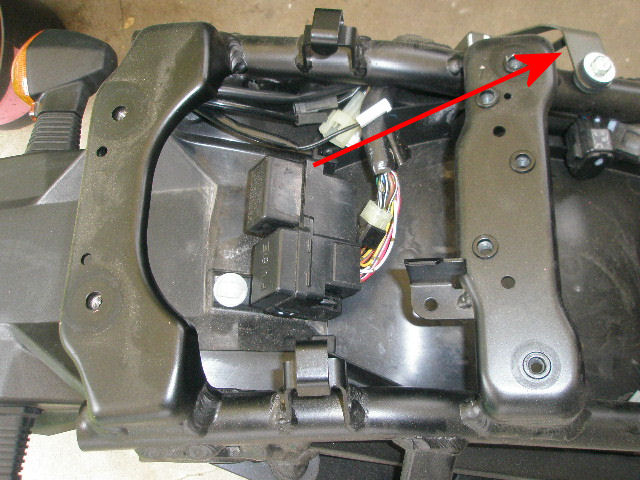
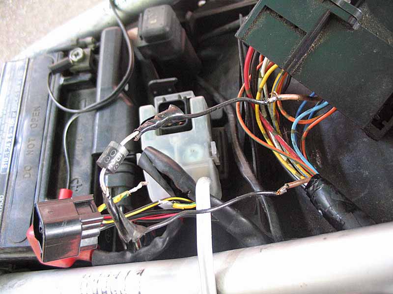
| A whole bunch of alarm wires "tapped" into this wiring block. Note every existing wire on this 4way block black! All I had to do here is unsolder the (black) alarm wires and repair the insulation. No joining required. |
 |
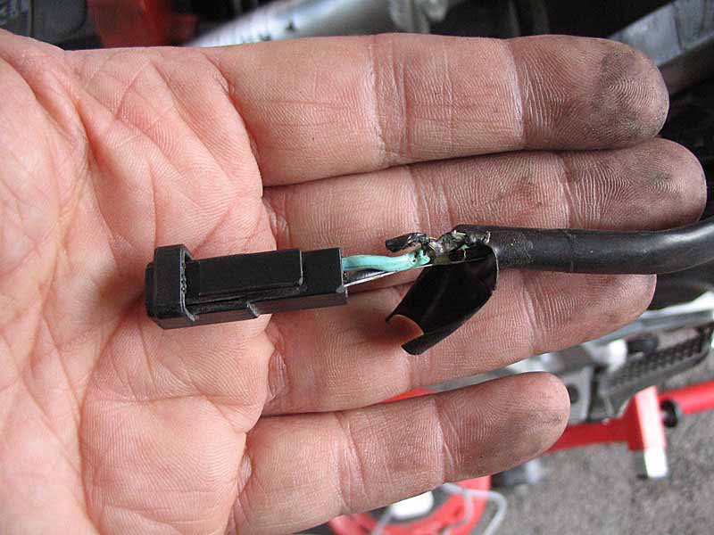
| Another intercepted connection found. This time on the brown leading to the relay/fuse blocks. Repaired as before with a new piece of wire, soldered and shrink wrapped. |
 |
| Not many wires left now. The next wire was the alarm wire which had the inline fuse. This was connected to a single black wire on the SV loom. Now this got confusing, as this wasn't a "tap", so therefore it had to be an intercept, but I couldn't find the rest of it. Being black didn't help as there are lots of black wires including those on the block I mentioned above. I removed the last "tap" wire from the indicator block (photo) and gave the bike a test. |
 |
| Well all looked good when I turned on the ignition, nothing went bang and no acrid smoke appeared. It was obvious though that the fuel pump was not priming. So clearly that last orphaned black wire had to connect to something. I tried joining it the each of the black wires on the 4way block. The pump burst into life on one connection. Happy face. I soldered up the joint and then did some testing. Whilst it worked if the ignition was already on, it didn't once the ignition was switched off and on again. Instead I got a flashing FI light. Bugger! |
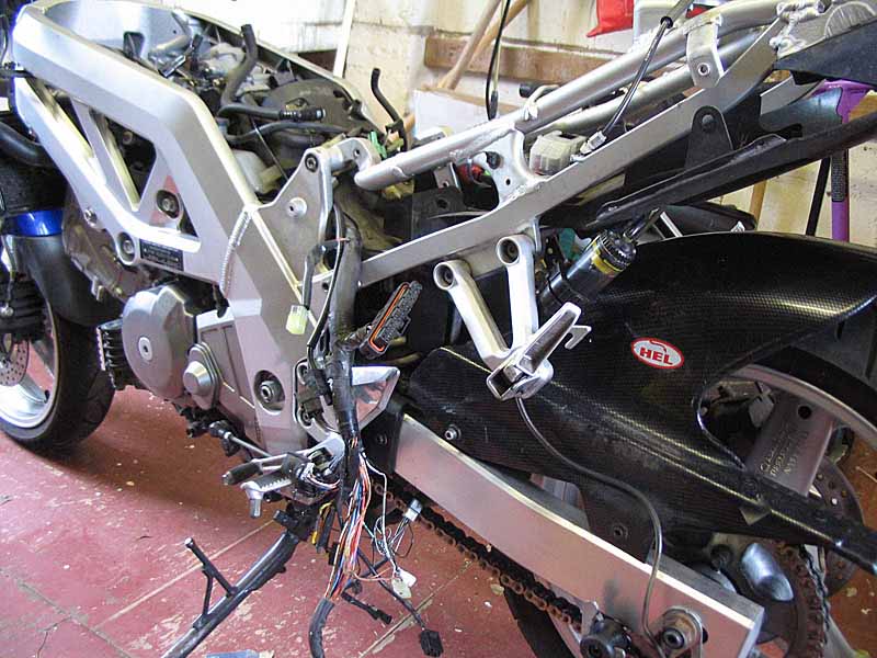 |
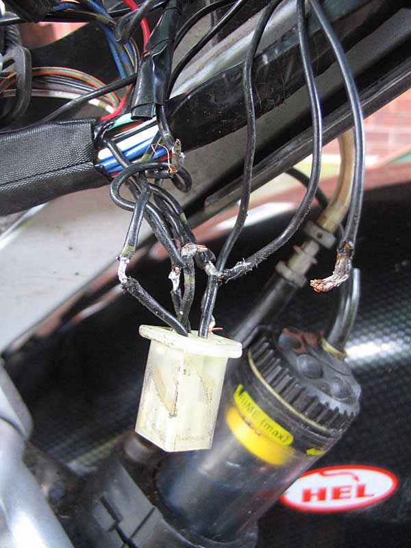
| I messed about for hours trying to work out where this mysterious wire was supposed to go. I decided to cut my losses and instead install my spare loom. It would probably be more reliable as well. As you can see from the photo, most of it was off anyhow. It's a pain removing some of the connectors mainly due to their location but it came out okay. I started to install the new loom at mid point where the tank hinges and noticed that I had one plug that didn't match anything. It seems that the fuel pump on my model has a 3way connector, on the loom it was 4way. Argh! I thought I'd checked all the connectors. |
 |
|
So back went the old loom. Installing is a lot
quicker than removing. And after a days work I was back where I started. I
looked at the new loom a bit more closely and compared it to the original.
The new loom had the 4way connector with the black wires and just ahead of
it was a single black with a 1way connector. This single wire was clearly the
one I couldn't find the other end of and the installer chopped off the
connector. So this wire goes nowhere and served a purpose unknown to me. I
got out the multimeter and consulted the wiring diagram. This single wire
gives a 12v feed which earlier helped provide the current to the fuel pump (In fact it was providing current to the fuel pump relay). I found another 12v
supply on one of the black wires on the 4way block and connected this to the
good wire on this block that activated the fuel relay, it worked. I tried
the ignition off and on test and still it worked. I did some more testing
and things were looking up until I used the kill switch and the engine
stopped as expected but the flashing FI light appeared again. Resetting the
ignition cleared it, in fact if you left the kill switch alone all was fine.
|
 |
|
At this point I was running out of time and
patience. I had a
new tyre to fit and only a week to go before a long trip to the lakes with
my London friends. I was also mentally fried. So I tidied up the wiring and
put the bike back together again for a test ride. It went fine. The next day
I rode the 3 miles into town to work, no issues. I made two further trips to Oswestry, 20 miles away and all good. I still use the kill switch
occasionally but it the flashing FI is soon fixed by resetting the kill
switch and ignition. Since then I have covered the trip to the lakes and
back, without incident. Perhaps this winter I'll go back over the loom and
work out where the circuit should be going as my solution is clearly not
right. Meantime I'll keep riding.
|
 |